Steel structure clamp

A steel structure and fixture technology, applied in the direction of manufacturing tools, workpiece clamping devices, etc., can solve the problems of difficult to meet the installation work of multiple beams, waste of materials, and prolong the installation period, so as to achieve convenient installation, enhanced reliability, and extended use. effect of life

Active Publication Date: 2020-10-09
浙江长锦建设有限公司
View PDF8 Cites 1 Cited by
  • Summary
  • Abstract
  • Description
  • Claims
  • Application Information

AI Technical Summary

Problems solved by technology

[0004] The above-mentioned existing technical solutions have the following defects: when installing the steel structure beams, the installer needs to install multiple parallel beams on the same construction column according to the installation requirements, and the clamps in the above patents are used once during installation. It can only meet the installation of one beam; it is difficult to meet the installation work of multiple beams, which leads to the installation personnel needing to install multiple clamps on the construction column to complete the installation of multiple beams; this not only causes waste of materials, but also Extended installation cycle

Method used


Image

  • Steel structure clamp
  • Steel structure clamp
  • Steel structure clamp

Examples


Embodiment Construction

[0033] The present invention will be described in further detail below in conjunction with the accompanying drawings.

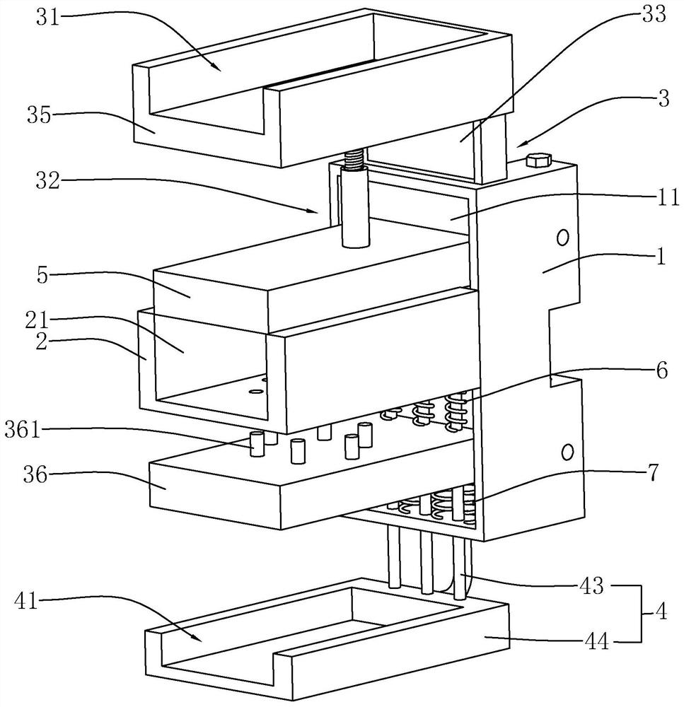
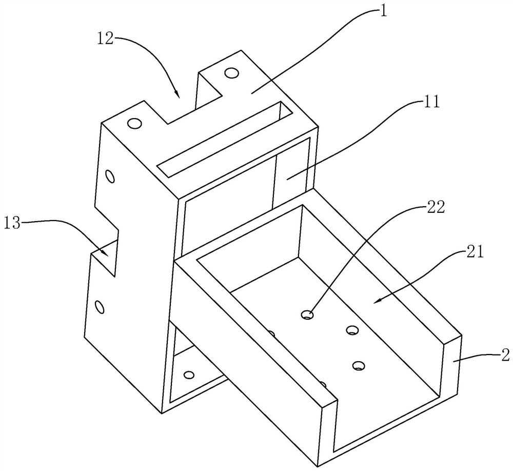
[0034] refer to figure 1 , is a steel structure fixture disclosed in the present invention, comprising a rectangular mounting base 1, a first bracket 2 placed horizontally is fixedly mounted on a vertical surface of the mounting base 1, and the upper end surface of the first bracket 2 is provided with The first clamping groove 21 with the opening facing upwards. The mounting base 1 is provided with a sliding slot 11 opening toward the first bracket 2 , and the second bracket 3 and the third bracket 4 are slidingly arranged in the sliding slot 11 along the vertical direction.

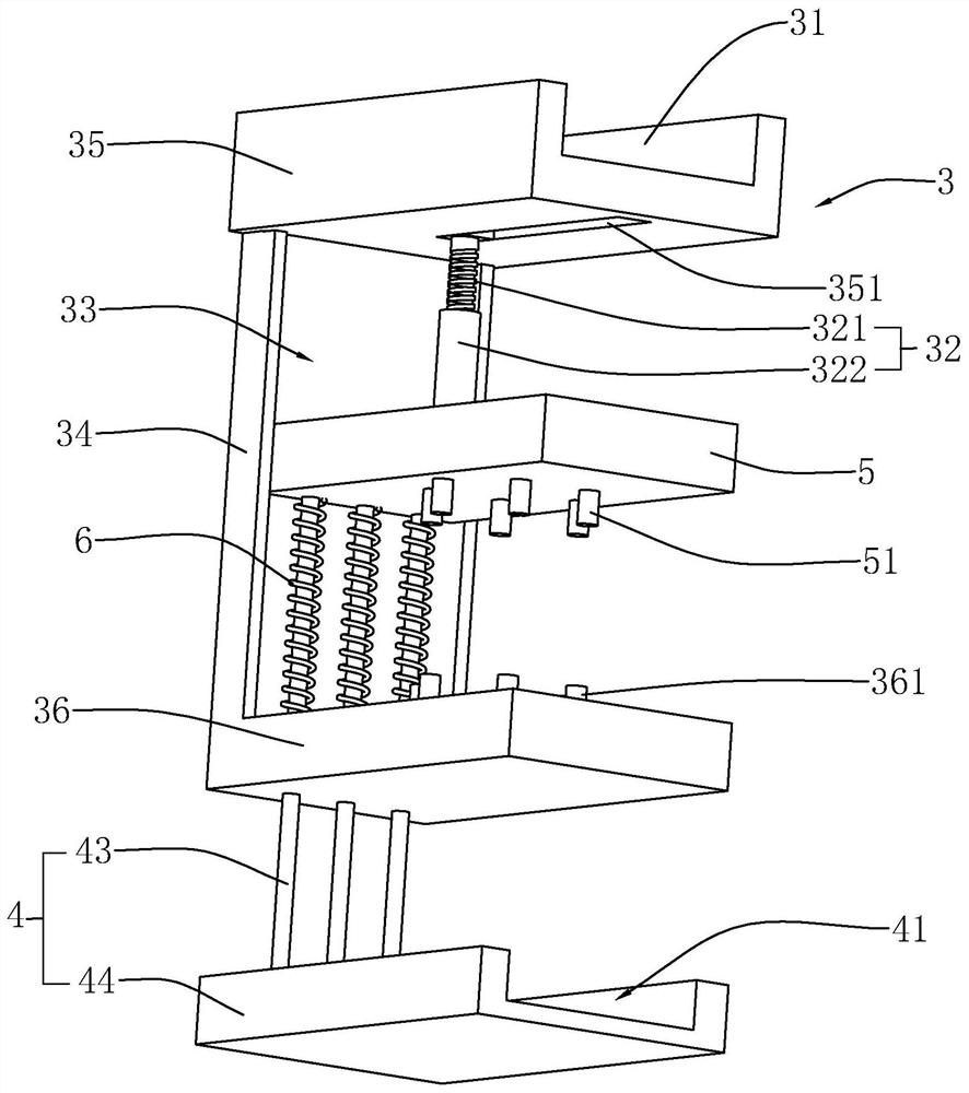
[0035] Such as figure 1 , figure 2 As shown, the second bracket 3 includes a main board 34 slidably arranged in the chute 11 , an upper cover 35 fixedly installed on the top of the main board 34 and a lower cover 36 fixedly installed on the bottom of the main board 34 . The upper c...


PUM


Abstract

The invention relates to a steel structure clamp, and relates to the technical field of building installation clamps. The steel structure clamp comprises a mounting base, a first support is arranged on the outer side wall of the mounting base, and a first clamping groove with an upward opening is formed in the first support; a sliding groove is formed in the mounting base, and a second support anda third support are slidably arranged in the sliding groove in the vertical direction; the top end of the second support penetrates out of an opening at the upper end of the sliding groove, and a second clamping groove is formed in the second support; the lower end of the third support penetrates out of an opening at the bottom of the sliding groove, and a third clamping groove with an upward opening is formed in the portion, penetrating out of the opening at the bottom of the sliding groove, of the third support; a pressing plate which penetrates out of a side opening of the sliding groove is formed in the upper end of the third support, and the pressing plate is located above the first clamping groove; and a fixing piece is arranged on the second support, the lower end of the fixing piece abuts against the pressing plate, and the fixing piece tightly presses the pressing plate on the first clamping groove. The steel structure clamp has the effects of being capable of meeting the mounting and fixing of multiple groups of steel structure cross beams at the same time, and stable in structure.

Description

technical field [0001] The invention relates to the technical field of construction installation fixtures, in particular to a steel structure fixture. Background technique [0002] Steel structure is a structure composed of steel materials, which is one of the main types of building structures. The structure is mainly composed of beam steel, steel column, steel truss and other components made of section steel and steel plate, and adopts rust removal and antirust processes such as silanization, pure manganese phosphating, washing and drying, and galvanizing. The components or components are usually connected by welds, bolts or rivets. Because of its light weight and easy construction, it is widely used in large factories, stadiums, super high-rises and other fields. [0003] In the prior art, the Chinese patent whose authorization notification number is CN206351424U discloses a special assembly fixture for steel structures, including a base, a column is connected to the top...

Claims


Application Information

Patent Timeline
Patent Type & Authority Applications(China)
IPC IPC(8): B25B11/02
CPCB25B11/02
Inventor 廖新辉张杠杠葛广建
Owner 浙江长锦建设有限公司
Why Eureka
Try Eureka