Camera self-cleaning device, camera system and camera system control method
A camera, self-cleaning technology, applied in the parts of TV systems, TVs, color TVs, etc., can solve the problems of dust shielding, raindrop adhesion, frost coverage, affecting the perception of the surrounding environment, affecting the imaging quality of the camera lens, etc. , to ensure high-performance operation, avoid overheating, and maintain cleanliness
- Summary
- Abstract
- Description
- Claims
- Application Information
AI Technical Summary
Problems solved by technology
Method used
Image
Examples
Embodiment 1
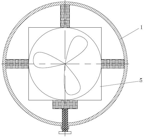
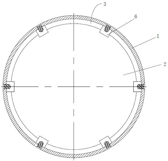
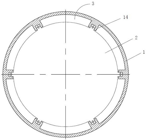
[0055] Such as figure 1 As shown, a camera self-cleaning device 100 proposed in Embodiment 1 of the present invention includes: a casing 1, a transparent cover 2, and a fan 4; the opposite first side and the second side of the casing 1 are respectively provided with An opening 11 and an air hole 12, the opening 11 is in the form of a neck; the transparent cover 2 is connected to the inner wall of the housing 1 near the opening 11 to cover the opening 11, and the transparent cover 2 A plurality of ventilation holes 3 are provided at intervals between the edge of the housing 1 and the inner wall of the housing 1; the fan 4 is arranged inside the housing 1 near the second side for One side blows air; wherein, the space between the fan 4 and the transparent cover plate 2 inside the housing 1 is used to set the camera module 200, and the inner wall of the housing 1 and the camera module 200 An air duct 5 can be formed therebetween, and the air duct 5 communicates with the ventilat...
Embodiment 2
[0079] Embodiment 2 of the present invention proposes a camera system, which includes: figure 1The camera self-cleaning device 100 is shown; the camera self-cleaning device 100 includes: a casing 1, an opening 11 and an air hole 12 are respectively provided on the opposite first side and the second side of the casing 1, and the opening 11 is a constricted mouth form; transparent cover plate 2, the transparent cover plate 2 is connected with the inner wall of the housing 1 near the opening 11 to cover the opening 11, and the edge of the transparent cover plate 2 is connected with the shell A plurality of ventilation holes 3 are arranged at intervals between the inner walls of the body 1; a fan 4 is arranged inside the housing 1 near the second side for blowing air to the first side; Wherein, the space between the fan 4 and the transparent cover plate 2 inside the casing 1 is used for setting the camera module 200, and the inner wall of the casing 1 and the camera module 200 can...
Embodiment 3
[0086] Embodiment 3 of the present invention proposes a camera system control method, which is stored in the controller of the camera system in the form of a program, or stored in the general controller of the device, vehicle, or robot that uses the camera system, such as Figure 6 As shown, the camera system control method includes:
[0087] 301. Acquire a first frame of image.
[0088] Specifically, the image is obtained by the camera module through the transparent cover. The specific method for the camera module to obtain the image is known to those skilled in the art, and will not be described in detail in the embodiment of the present invention.
[0089] 302. Perform brightness detection and out-of-focus detection on the first frame of image.
[0090] Specifically, since the camera self-cleaning device protects the camera module, dust, water droplets, frost, and fog all fall on the camera self-cleaning device, especially on the transparent cover, and then the camera modu...
PUM
 Abstract
Description
Claims
Application Information
 - Generate Ideas
- Intellectual Property
- Life Sciences
- Materials
- Tech Scout
- Unparalleled Data Quality
- Higher Quality Content
- 60% Fewer Hallucinations
Browse by: Latest US Patents, China's latest patents, Technical Efficacy Thesaurus, Application Domain, Technology Topic, Popular Technical Reports.
© 2025 PatSnap. All rights reserved.Legal|Privacy policy|Modern Slavery Act Transparency Statement|Sitemap|About US| Contact US: help@patsnap.com


