


Quick Research
Generate reliable direction feasibility study reports for your R&D in just a few steps.

Technical Q&A
Discover and master advanced knowledge NOW. Basics, ideas, possibilities, all at once.

Find Solutions
As an expert in R&D theories, this can generate solutions to your technical problems instantly.

Evaluate Feasibility
Analyze your overall solution with one click, know your potential R&D risks in advance.

Monitor Landscape
Get weekly tech updates, stay abreast of the latest tech innovations and key insights.
Standing anti-stretching hip training device
A training device and standing technology, applied in the field of training devices, can solve problems such as troublesome operation
- Summary
- Abstract
- Description
- Claims
- Application Information
AI Technical Summary
Problems solved by technology
Method used
Image


Examples
Embodiment 1
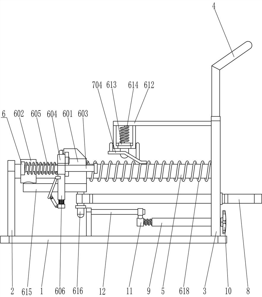
[0023] see Figure 1-Figure 5 , a standing resistance hip extension training device, comprising a base plate 1, a support plate 2, a mounting plate 3, a handrail 4, a first guide rod 5, a rope release assembly 6, a rope retraction assembly 7, an elastic rope 8 and a limiter Position block 801, support plate 2 is fixed on the top left, front and rear sides of bottom plate 1, mounting plate 3 is fixed on the right side, front and rear sides on the top of bottom plate 1, and armrest 4 is fixed between the top of the mounting plate 3 on the front and rear sides. , a first guide rod 5 is fixedly connected between the upper left side of the front mounting plate 3 and the upper right side of the front support plate 2, and the upper left side of the rear mounting plate 3 and the upper right side of the rear support plate 2 A first guide rod 5 is also fixed between the first guide rods 5 and the mounting plate 3. A rope release assembly 6 is provided between the first guide rod 5 and t...
Embodiment 2
[0030] see figure 1 and figure 2 The main difference between this embodiment and embodiment 1 is that this embodiment also includes an internal threaded pipe 9, a knob 10, a screw 11, a second guide rod 12 and a third slider 13, and the top left side of the bottom plate 1 Two second guide rods 12 are fixedly connected to the front and rear parts, and a third slider 13 is slidably arranged between the two second guide rods 12 on the front side and the two second guide rods 12 on the rear side. The third slider 13 cooperates with the movable rod 616, the middle of the bottom of the third slider 13 is fixedly connected with the screw rod 11, and the middle of the lower part of the mounting plate 3 is rotationally connected with an internally threaded pipe 9, and the internally threaded pipe 9 is located below the elastic pull cord 8 , the screw rod 11 is located in the internally threaded pipe 9 to cooperate with it, and the right end of the internally threaded pipe 9 is fixedl...
Embodiment 3
[0033] see image 3 , Figure 5 and Image 6 Compared with Embodiment 1 and Embodiment 2, the main difference of this embodiment is that in this embodiment, it also includes the second clamping lever 14, the seventh spring 15, the rotating plate 16 and the connecting rod 17, and the bottom of the rectangular rod 603 is opened in the middle. There is a second clamping slot 18, and the hollow pull rod 606 is slidingly provided with a second clamping rod 14, the top of the second clamping rod 14 is located in the second clamping groove 18 to cooperate with it, and the inner bottom of the second clamping rod 14 is connected to the bottom of the hollow rod 606 The seventh spring 15 is wound around, the second clamping rod 14 is hinged with a connecting rod 17 at the lower left side, and the upper left side of the hollow pull rod 606 is hinged with a rotating plate 16, and the lower part of the right side of the rotating plate 16 is connected with the connecting rod 17 at the end. ...
PUM
 Abstract
Description
Claims
Application Information
 - R&D Engineer
- R&D Manager
- IP Professional
- Industry Leading Data Capabilities
- Powerful AI technology
- Patent DNA Extraction
Browse by: Latest US Patents, China's latest patents, Technical Efficacy Thesaurus, Application Domain, Technology Topic, Popular Technical Reports.
© 2024 PatSnap. All rights reserved.Legal|Privacy policy|Modern Slavery Act Transparency Statement|Sitemap|About US| Contact US: help@patsnap.com