


Quick Research
Generate reliable direction feasibility study reports for your R&D in just a few steps.

Technical Q&A
Discover and master advanced knowledge NOW. Basics, ideas, possibilities, all at once.

Find Solutions
As an expert in R&D theories, this can generate solutions to your technical problems instantly.

Evaluate Feasibility
Analyze your overall solution with one click, know your potential R&D risks in advance.

Monitor Landscape
Get weekly tech updates, stay abreast of the latest tech innovations and key insights.
Fixed spray irrigation machine for garden lawn maintenance and use method
A fixed type, sprinkler irrigation technology, applied in the field of garden lawn sprinkler irrigation, can solve the problems of lack of agitation in pipelines, pipeline blockage, inability to reduce workload, etc., and achieve the effect of improving efficiency and effect.
- Summary
- Abstract
- Description
- Claims
- Application Information
AI Technical Summary
Problems solved by technology
Method used
Image

Examples
Embodiment 1
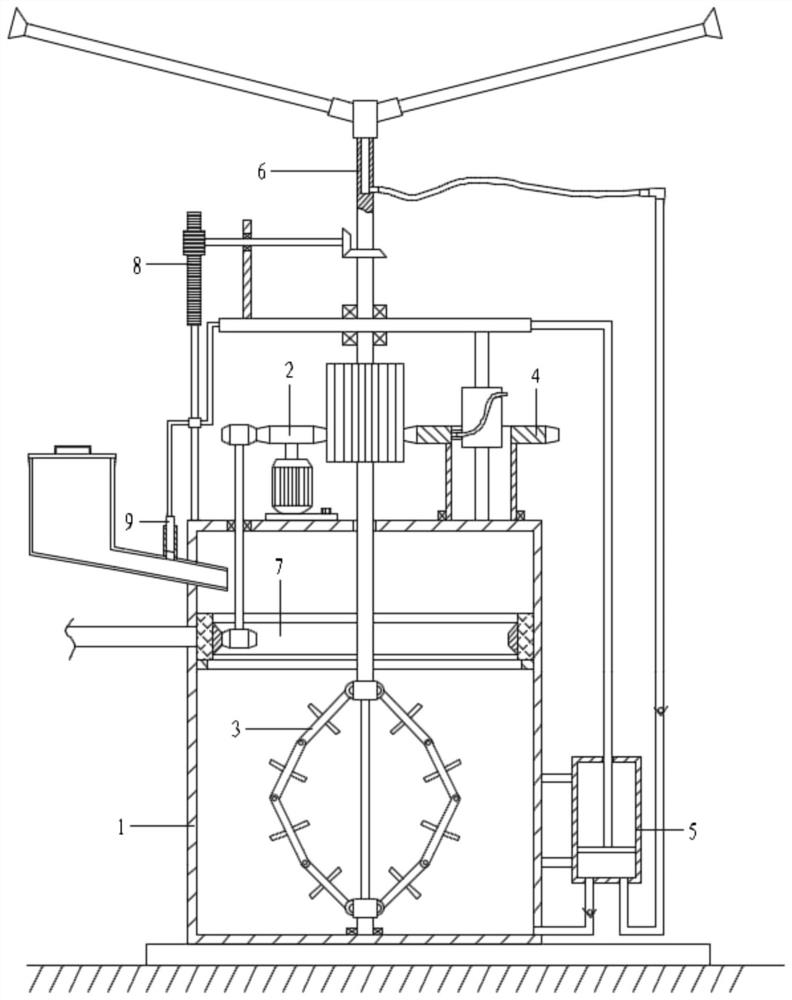
[0072] With reference to the accompanying drawings, a fixed sprinkler irrigation machine for garden and lawn maintenance includes a tank assembly 1, a drive assembly 2, a stirring assembly 3, a lifting assembly 4, a liquid upper assembly 5 and a sprinkler assembly 6;
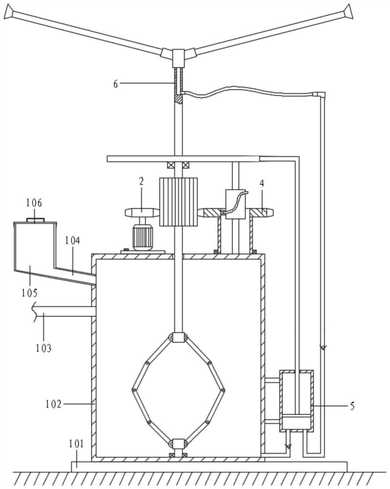
[0073] The tank assembly 1 includes a base 101, a mixing tank 102, a water inlet pipe 103, a medicine feeding pipe 104, a medicine storage tank 105 and a cover 106; The left side is connected with a water inlet pipe 103; the medicine storage tank 105 is also connected to the upper left side of the mixing tank 102 through the medicine inlet pipe 104, and is located above the water inlet pipe 103; the top of the medicine storage tank 105 is equipped with a cover 106;
[0074] The top of the mixing tank 102 is provided with a driving assembly 2, the right side of the driving assembly 2 is equipped with a lifting assembly 4, and the top of the lifting assembly 4 is provided with a sprinkler assembly 6; the bottom end...
Embodiment 2
[0076] With reference to the accompanying drawings, a fixed sprinkler irrigation machine for garden and lawn maintenance includes a tank assembly 1, a drive assembly 2, a stirring assembly 3, a lifting assembly 4, a liquid upper assembly 5 and a sprinkler assembly 6;
[0077] The tank assembly 1 includes a base 101, a mixing tank 102, a water inlet pipe 103, a medicine feeding pipe 104, a medicine storage tank 105 and a cover 106; The left side is connected with a water inlet pipe 103; the medicine storage tank 105 is also connected to the upper left side of the mixing tank 102 through the medicine inlet pipe 104, and is located above the water inlet pipe 103; the top of the medicine storage tank 105 is equipped with a cover 106;
[0078] The top of the mixing tank 102 is provided with a driving assembly 2, the right side of the driving assembly 2 is equipped with a lifting assembly 4, and the top of the lifting assembly 4 is provided with a sprinkler assembly 6; the bottom end...
Embodiment 3
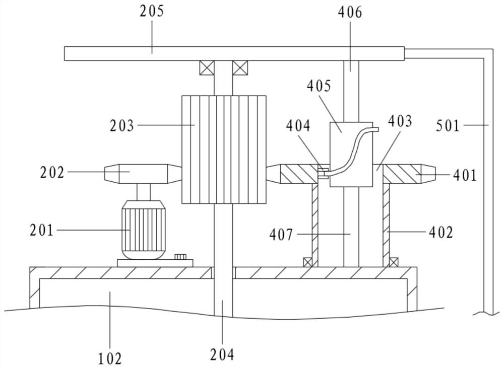
[0103] In Example 2, the driving of the stirring assembly 3 is completed by the No. 1 rotating shaft 204, and the lower mounting base 302 and the No. 2 rotating shaft 303 below are driven by the multi-section rod group 304 to rotate, so that the load is relatively large, and there will be materials during actual stirring. Resistance and other component loads, the first rotating shaft 204 is only connected by the top bearing, which may make the first rotating shaft 204 unstable;
[0104] Therefore, on the basis of Embodiment 2, a square rod 306 is also included;
[0105] The lower part of the first rotating shaft 204 is processed with a groove, and the upper mounting base 301 has a mounting hole; the top of the lower mounting base 302 is connected with a square rod 306; the square rod 306 passes through the mounting hole upwards and extends into the groove;
[0106] Specifically, the cross section of the groove and the mounting hole are both square holes corresponding to the sq...
PUM
 Abstract
Description
Claims
Application Information
 - R&D Engineer
- R&D Manager
- IP Professional
- Industry Leading Data Capabilities
- Powerful AI technology
- Patent DNA Extraction
Browse by: Latest US Patents, China's latest patents, Technical Efficacy Thesaurus, Application Domain, Technology Topic, Popular Technical Reports.
© 2024 PatSnap. All rights reserved.Legal|Privacy policy|Modern Slavery Act Transparency Statement|Sitemap|About US| Contact US: help@patsnap.com