Clamp structure for cable end and auxiliary device with the clamp structure

A technology of cable ends and auxiliary devices, which is applied in the direction of circuits, electrical components, circuit/collector components, etc., can solve the problems of potential safety hazards, time-consuming and labor-intensive problems, improve efficiency, reduce labor, and facilitate cable work areas Effect

Active Publication Date: 2021-06-01
江西博展自动化科技有限公司
View PDF0 Cites 0 Cited by
  • Summary
  • Abstract
  • Description
  • Claims
  • Application Information

AI Technical Summary

Problems solved by technology

It can be seen that due to the lack of special auxiliary devices, the existing manual operation is not only time-consuming and laborious, but also has potential safety hazards

Method used


Image

  • Clamp structure for cable end and auxiliary device with the clamp structure
  • Clamp structure for cable end and auxiliary device with the clamp structure
  • Clamp structure for cable end and auxiliary device with the clamp structure

Examples


Embodiment 1

[0063] Such as Figure 1 to Figure 19 As shown, the cable end is equipped with a clamp structure, including an end clamp frame 1;

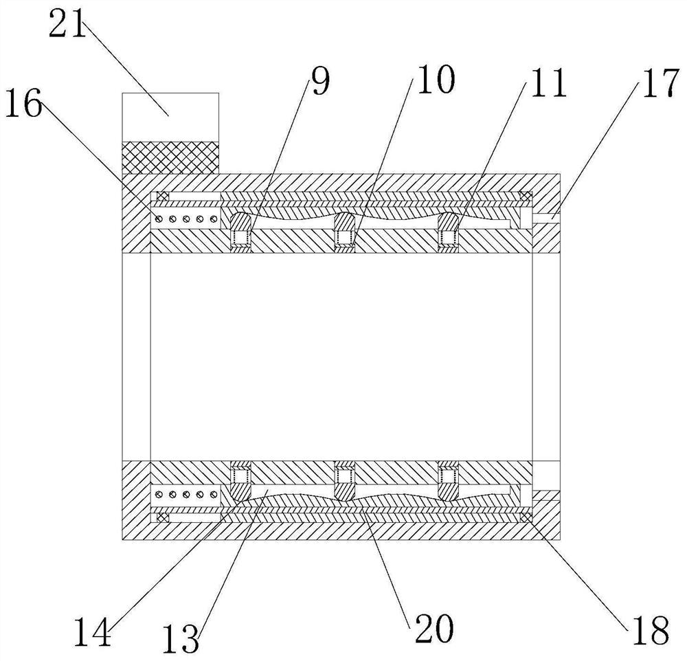
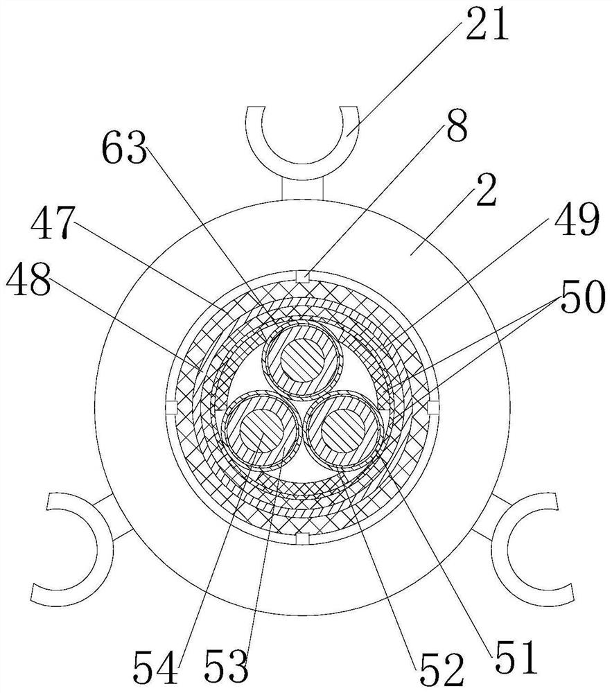
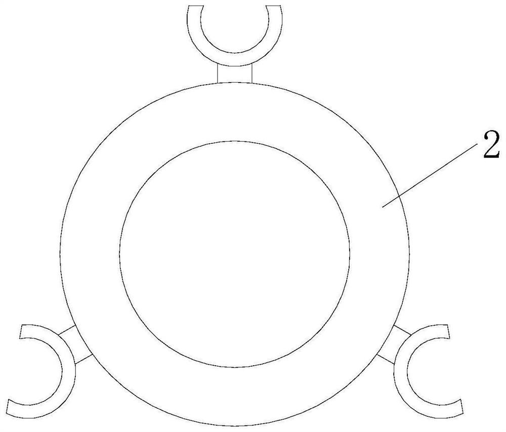
[0064] An end clamping tube 2 is installed on the end clamp frame 1, and the end clamping tube 2 has a hollow end clamping area 3 along its axial direction, and the end clamping area 3 runs through the inner end and the outer end of the end clamping tube 2. There is a hollow interlocking movable cavity 4 inside the tube wall of the holding tube 2, and the interlocking movable cavity 4 divides the tube wall of the terminal clamping tube 2 into the terminal inner tube section 5 and the terminal outer tube section 6;

[0065] There are several groups of interlocking port groups on the end inner pipe section 5, each group of interlocking port groups has at least two interlocking ports 7 communicating with the interlocking movable chamber 4, and the interlocking ports 7 are slidably provided with The interlocking slider 8, the middle part of the inter...

Embodiment 2

[0072] This embodiment makes the following further limitations on the basis of Embodiment 1: the end clamping tube 2 is provided with a lower clamping limit ring 18 and a high clamping limit ring 18 located in the interlocking movable chamber 4 . The positioning ring 19 , the lower clamping limiting ring 18 and the upper clamping limiting ring 19 are respectively located on both sides of the interlocking movable tube 12 .

[0073] In this embodiment, the terminal clamping vent hole 17 can be arranged in the area surrounded by the lower clamping limiting ring 18 .

Embodiment 3

[0075] This embodiment makes the following further limitations on the basis of Embodiment 1: the end clamping tube 2 is provided with an end clamping guide rod that is located in the interlocking activity chamber 4 and runs through both ends of the interlocking activity tube 12 20. The interlocking movable tube 12 can move axially relative to the clamping guide rod 20 at the end.

[0076] In this embodiment, there may be two terminal clamping guide rods 20 .


PUM


Abstract

The invention discloses a clamp structure for a cable end and an auxiliary device with the clamp structure. The clamp structure includes a terminal clamp frame; a terminal clamping pipe is installed on the terminal clamp frame; several groups of interlocking port groups are provided on the terminal inner pipe section , each group of interlocking port groups has at least two interlocking ports communicating with the interlocking movable chamber, and interlocking sliders are slidably arranged at the interlocking port; ; When the interlocking movable tube is moved so that the high part of the groove is facing the interlocking slider, the inner side of the interlocking slider is located in the terminal clamping area; The end of the clip holds the vent. The invention can realize fast positioning and quick withdrawal of the cable end. Among them, through the setting of the cable hook, the three-phase cable can be suspended and positioned when the three-phase cable process is separated, so as to improve the convenience and stability of the operation.

Description

technical field [0001] The invention belongs to the technical field of cable head production, and in particular relates to a clamp structure for a cable end and an auxiliary device with the clamp structure. Background technique [0002] The production of cable head is an important link in the cable laying project, which directly affects the quality of the entire project and the reliability, safety and effectiveness of building electricity. At present, the production and installation methods of cable terminals include dry-pack type (wrapped with insulating tape), pouring type (epoxy resin pouring) and heat-shrinkable type (using heat-shrinkable cable accessories), etc. The production process of the first two types of cable terminals is relatively It is cumbersome, difficult to operate, and there are also defects such as short life of the joint and unstable quality. Therefore, in practice, the heat shrinkable type is often used to make the terminal cable head. [0003] The pr...

Claims


Application Information

Patent Timeline
Patent Type & Authority Patents(China)
IPC IPC(8): H01R43/00H01R43/28
CPCH01R43/00H01R43/28
Inventor 张雪松
Owner 江西博展自动化科技有限公司
Why Eureka
Try Eureka