
Display device

A display device and main display technology, which is applied to identify devices, instruments, etc., and can solve problems such as unclear display screens of knobs

Pending Publication Date: 2020-09-25
SHANGHAI AVIC OPTOELECTRONICS
View PDF12 Cites 1 Cited by
  • Summary
  • Abstract
  • Description
  • Claims
  • Application Information

AI Technical Summary

Problems solved by technology

[0004] The embodiment of the present invention provides a display device to solve the problem that the display screen of the rotary knob assembled on the existing vehicle display screen is not clear

Method used


Image

  • Display device
  • Display device
  • Display device

Examples


Embodiment Construction

[0019] The present invention will be further described in detail below in conjunction with the accompanying drawings and embodiments. It should be understood that the specific embodiments described here are only used to explain the present invention, but not to limit the present invention. In addition, it should be noted that, for the convenience of description, only some structures related to the present invention are shown in the drawings but not all structures.

[0020] In the prior art, as described in the above-mentioned background technology, when displaying part of the picture through the surface of the knob on the display screen, generally by setting an optical fiber panel on the surface of the knob, the picture of the display screen is directly transmitted out of the surface of the knob, but the fiber optic panel and the surface of the knob There are media gaps such as sensors and optical glue between the display screens, which cause the light from different pixel uni...


PUM


Abstract

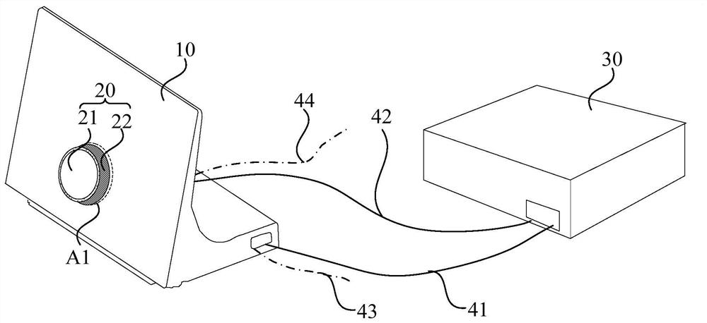
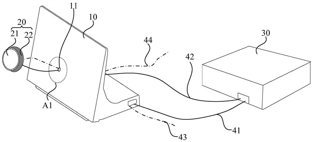
The invention discloses a display device. The display device comprises a main display panel, a knob panel assembly and a main controller, the knob panel assembly comprises an auxiliary display panel and a knob assembly for fixing the auxiliary display panel; the main controller is connected with the main display panel through a first transmission line and is used for sending first image information to the main display panel, so that the main display panel displays a first image; the knob panel assembly is fixed on the light emitting side of the main display panel; and an area covered by the vertical projection of the knob panel assembly on the plane where the main display panel is located is the first area of the main display panel. A first through hole penetrating through the main displaypanel is formed in the first area; the main controller is connected with the auxiliary display panel through a second transmission line penetrating through the first through hole and used for sendingsecond image information to the auxiliary display panel, so that the auxiliary display panel displays a second image. The invention provides the display device to solve the problem that a knob assembled on an existing vehicle-mounted display screen displays an unclear picture.

Description

technical field [0001] The present invention relates to the field of display technology, in particular to a display device. Background technique [0002] At present, most of the electronic products inside the car can be operated through knobs or buttons, but with the application of large-size display screens in cars, the interior styling puts forward new requirements for the design of the knobs. on the display. [0003] The knob as a whole will occupy part of the display area of ​​the display screen, so part of the screen can be displayed through the surface of the knob. In the prior art, when the knob is assembled on the surface of the display screen, the surface of the knob is often designed with an optical fiber panel to directly transmit the picture of the display screen to the surface of the knob, so that the surface of the knob displays the picture displayed on the screen at the position. However, there are media gaps such as sensors, optical glue, and cover glass be...

Claims


Application Information

Patent Timeline
Patent Type & Authority Applications(China)
IPC IPC(8): G09F9/30
CPCG09F9/30
Inventor 王铭秦锋
Owner SHANGHAI AVIC OPTOELECTRONICS
Learn More