
Full-automatic laser mark spraying machine with accurate positioning function

A fully automatic, inkjet printer technology, applied in the field of laser inkjet printing, can solve the problems of control cabinet heating, reducing work efficiency, affecting the efficiency of galvanometer adjustment, etc., to reduce adjustment time, improve work efficiency, and reduce work hidden dangers. Effect

Inactive Publication Date: 2020-09-25
苏州郎旭志远科技有限公司
View PDF7 Cites 0 Cited by
  • Summary
  • Abstract
  • Description
  • Claims
  • Application Information

AI Technical Summary

Problems solved by technology

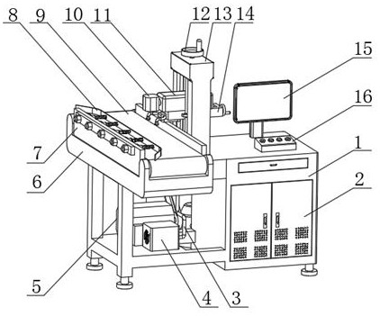
[0003] There are still certain disadvantages in the use of existing laser inkjet printers. First, when the existing laser inkjet printers are in use, the Z-axis slide rail used to adjust the height of the laser transmitter and the vibrating mirror is a single slide rail For pillars, only one end of the X-axis slide rail is embedded in the Z-axis slide rail to move, so that when adjusting the height and left-right distance of the galvanometer, the X-axis slide rail is prone to irregular shaking and affects the efficiency of the galvanometer adjustment, thereby reducing work efficiency ; Second, in the process of laser marking the object, smoke will be generated due to burning, and the gas will cause certain harm to the user, and there is a great potential safety hazard; third, during the transmission of the object on the conveyor belt, the object Offset will occur, resulting in inaccurate laser marking, resulting in many defective products and affecting production efficiency; fourth, after the main body of the equipment has been working for a long time, its control cabinet will heat up. When the heat is too high, It will lead to the instability of the working voltage of the main body of the equipment, affect the power of the laser, and cause unqualified coding. For this reason, we propose a fully automatic laser inkjet printer with precise positioning

Method used


Image

  • Full-automatic laser mark spraying machine with accurate positioning function
  • Full-automatic laser mark spraying machine with accurate positioning function
  • Full-automatic laser mark spraying machine with accurate positioning function

Examples


Embodiment Construction

[0030] The following will clearly and completely describe the technical solutions in the embodiments of the present invention with reference to the accompanying drawings in the embodiments of the present invention. Obviously, the described embodiments are only some, not all, embodiments of the present invention. Based on the embodiments of the present invention, all other embodiments obtained by persons of ordinary skill in the art without making creative efforts belong to the protection scope of the present invention.

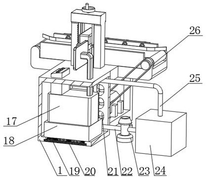
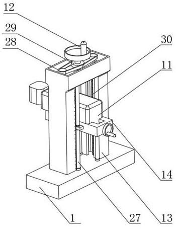
[0031] see Figure 1-7 , a fully automatic laser inkjet printer with precise positioning, including a device main body 1, an operation button 16 is arranged on the upper end of the device main body 1, and a display screen 15 is provided at the rear end of the operation button 16, and the model of the display screen 15 is BD-C215TM , the front end of the equipment main body 1 is provided with a cabinet door 2, the side end of the display screen 15 is provided w...


PUM


Abstract

The invention relates to the field of laser mark spraying, and discloses a full-automatic laser mark spraying machine with an accurate positioning function. The laser mark spraying machine comprises an equipment main body, wherein operation buttons are arranged at the upper end of the equipment main body, a display screen is arranged at the rear ends of the operation buttons, a cabinet door is arranged at the front end of the equipment main body, a Z-axis sliding rail is arranged at the side end of the display screen, a rotating wheel is arranged at the upper end of the Z-axis sliding rail, and an X-axis sliding rail is arranged on the inner side of the Z-axis sliding rail. According to the laser mark spraying machine, the X-axis sliding rail is stably embedded into the double-Z-axis sliding rail through the double-Z-axis sliding rail, and irregular shaking of a galvanometer in the adjusting process due to the single structure of the X-axis sliding rail and the double-Z-axis sliding rail is avoided; a purifying box is matched with suction pipes and suction openings so that smoke generated by laser marking can be sucked into the purifying box for filtering at the first time; U-shaped water pipes are matched with a fan so that heat dissipation can be effectively carried out on a control cabinet; and a limiting plate is matched with springs and movable rods so that laser marking can be stably and neatly carried out on objects needing to be machined on a conveying belt.

Description

technical field [0001] The invention relates to the field of laser coding, in particular to a fully automatic laser coding machine with precise positioning. Background technique [0002] Laser inkjet printers are widely used in food processing, building materials processing, pharmaceutical packaging, etc. It has the advantages of good coding effect, not easy to drop, and clear fonts. [0003] There are still certain disadvantages in the use of existing laser inkjet printers. First, when the existing laser inkjet printers are in use, the Z-axis slide rail used to adjust the height of the laser transmitter and the vibrating mirror is a single slide rail For pillars, only one end of the X-axis slide rail is embedded in the Z-axis slide rail to move, so that when adjusting the height and left-right distance of the galvanometer, the X-axis slide rail is prone to irregular shaking and affects the efficiency of the galvanometer adjustment, thereby reducing work efficiency ; Second...

Claims


Application Information

Patent Timeline
Patent Type & Authority Applications(China)
IPC IPC(8): B23K26/16B23K26/362B23K26/70
CPCB23K26/16B23K26/362B23K26/702B23K26/703
Inventor 马金平
Owner 苏州郎旭志远科技有限公司
Learn More