
Liquid level switch

A technology of liquid level switch and micro switch, which is applied in the direction of buoy liquid level indicator, liquid/fluid solid measurement, robot floating motion actuation, etc. problems, to achieve the effect of free maintenance, online self-inspection, and avoiding false alarms

Active Publication Date: 2020-09-22
潍坊亚峰化工仪表有限公司
View PDF7 Cites 0 Cited by
  • Summary
  • Abstract
  • Description
  • Claims
  • Application Information

AI Technical Summary

Problems solved by technology

[0007] The liquid level switches in the prior art all adopt the integral connection of the floating ball and the hard guide rod of the inner magnetic steel assembly, and the position of the liquid level control is not easy to adjust. The length of the rod is usually relatively long, so it will inevitably cause the floating ball to sway left and right. The inner magnetic steel component at the upper end is often stuck due to eccentricity or excessive viscosity. It needs to be disassembled, cleaned and maintained regularly, and online self-inspection and Maintenance-free
For example, although the Chinese patent CN206039306 has designed a self-inspection structure, there is a potential safety hazard of leakage in this structure. This design uses the method of pulling the handle to move the self-inspection device upwards to drive the floating ball linkage, and a compression nut is used between the handle rod and the outside world. Sealing, without considering the actual operability. If the compression nut is too tight, the sealing effect will be achieved, but the handle rod will also be tightly held and it will be difficult to operate and move up and down. If the compression nut is too loose, it will inevitably cause damage to the tank. Leakage of liquid or volatile gas causes potential safety hazards. This structure has major technical defects. At the same time, the patent also has the problem that the floating ball is easily bonded to the inner guide rod due to its high viscosity. The sensor switch installed on the side cannot be self-maintained. Defects such as increase in the volume of the external buoy of the mechanism and increase in cost
[0008] The liquid level switch in the prior art, because the connecting rod is long, has high requirements on the neutrality of the on-site installation. If the installation is inclined, the connecting rod will inevitably be stuck, so the controllable length of this type of liquid level switch is usually small. Moreover, most of the control positions cannot be adjusted, the cost of materials is relatively high, the failure rate is high, and the control accuracy is poor
[0009] In the liquid level switch of the prior art, because the weight of the float is too light, and the structure of the float and the connecting rod is integrated, in order to limit the range of the float, it usually needs to be equipped with an external buoy installed on the side, and the switch is installed on the side. above the square outer buoy
For example, the patent CN208432911U has increased a lot of costs, and many crude oil storage tanks cannot be welded on site, so the singleness of the installation method also limits the realization of the control function
At the same time, the floating ball is too light, and it is easy to fluctuate up and down due to the fluctuation of the liquid level in the storage tank, and it is easy to cause the switch to malfunction and cause false alarms.

Method used


Image

  • Liquid level switch
  • Liquid level switch
  • Liquid level switch

Examples


Embodiment Construction

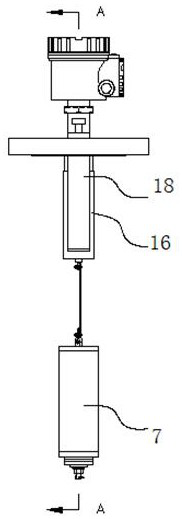
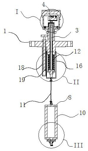
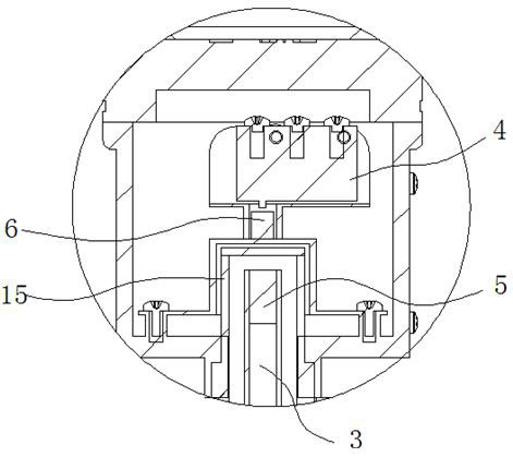
[0029] Such as Figure 1 to Figure 5 As shown, a liquid level switch includes a mounting base 1 installed on the storage tank, the mounting base 1 is provided with a guide hole, and an inner guide rod 3 is movably installed in the guide hole, and the mounting base is fixed on the A micro switch 4 is installed, and an inner magnetic steel 5 is fixedly installed on the upper end of the inner guide rod 1, and the inner magnetic steel 5 and the micro switch 4 are provided between the inner magnetic steel 5 and the micro switch 4 to trigger the micro switch when moving upward The upper drive magnet 6, the magnetic pole of the lower end of the upper drive magnet 6 is the same as the magnetic pole of the upper end of the inner magnet 5; it also includes a floating mechanism that drives the inner guide rod to move upward when the liquid level in the storage tank rises. mechanism. The inner magnet and the upper drive magnet adopt the principle of magnetic coupling drive. The inner mag...


PUM


Abstract

The invention relates to a liquid level switch, which comprises a mounting seat mounted on a storage tank, wherein a guide hole is formed in the mounting seat, an inner guide rod is movably mounted inthe guide hole, a microswitch is fixedly installed on the mounting seat, inner magnetic steel is fixedly installed at the upper end of the inner guide rod, upper driving magnetic steel capable of triggering the microswitch when moving upwards is arranged between the inner magnetic steel and the microswitch, the magnetic pole of the lower end of the upper driving magnetic steel is the same as themagnetic pole of the upper end of the inner magnetic steel, the liquid level switch further comprises a floating mechanism for driving the inner guide rod to move upwards when the liquid level in thestorage tank rises, and the floating mechanism comprises a sinking barrel and a tension compensation mechanism, so that false alarm caused by inaccurate density can be avoided, the control precision can be effectively improved, and online self-inspection and disassembly-free maintenance of the liquid level can be achieved.

Description

technical field [0001] The invention relates to a liquid level switch. Background technique [0002] At present, for some large crude oil or viscous medium storage tanks or reaction tanks, most of the float type liquid level gauges cannot be used because of their high viscosity. The buoy pointer liquid level gauge with on-site mechanical pointer display is mostly used in this application environment. If the material is too high, it will cause a safety hazard of overflow irrigation. The human eye pointer scale is used to observe and measure the liquid level and make a judgment, and the pump valve is manually cut off to achieve the purpose of controlling the liquid level of the raw material in the storage tank. This operation method brings The labor cost is very high, and because the storage tank is generally high, it is not conducive to observation, and its safety factor is not high, and most of them rely on the sense of responsibility of the on-site personnel. [0003] At p...

Claims


Application Information

Patent Timeline
Patent Type & Authority Applications(China)
IPC IPC(8): H01H36/02G01F23/44G01F25/00G08B21/18
CPCH01H36/02G01F23/44G08B21/18G01F25/20Y02E30/30
Inventor 姜夏旭孙连锡孟祥琦
Owner 潍坊亚峰化工仪表有限公司
Learn More