A municipal sewage pipe cleaning device

A technology for cleaning devices and municipal sewage, applied to water supply devices, cleaning sewer pipes, waterway systems, etc., can solve problems such as poor working environment, low work efficiency, and impossible to clean up

Active Publication Date: 2021-04-20
四川九鼎建筑工程集团有限公司
View PDF9 Cites 0 Cited by
  • Summary
  • Abstract
  • Description
  • Claims
  • Application Information

AI Technical Summary

Problems solved by technology

Such a small pipeline dredging cannot be operated manually. The existing sedimentation sludge recovery device in the drainage pipeline is that the staff holds the suction hose nozzle connected to the recovery tank equipped with an air suction pump on the ground and enters the drainage pipeline to remove the sediment. The sludge is recovered from the suction hose nozzle to the recovery tank on the ground; because the working environment in the drainage pipe is poor and emits a strong odor, it is difficult to work for a long time and the work efficiency is low. In the knot state, it is still difficult to suck and recover from the hose nozzle only by suction, and it is impossible to clean up all the settled sludge from the sludge in the drainage pipe
Although there is a dredging device in the current research, it is easy to produce wheel slippage when driving in the sewage pipe, resulting in the situation that the cleaning work cannot be carried out. Therefore, there is a need for a municipal sewage pipe cleaning device that will not slip when driving in the sewage pipe

Method used


Image

  • A municipal sewage pipe cleaning device
  • A municipal sewage pipe cleaning device
  • A municipal sewage pipe cleaning device

Examples


Embodiment 1

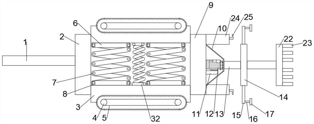
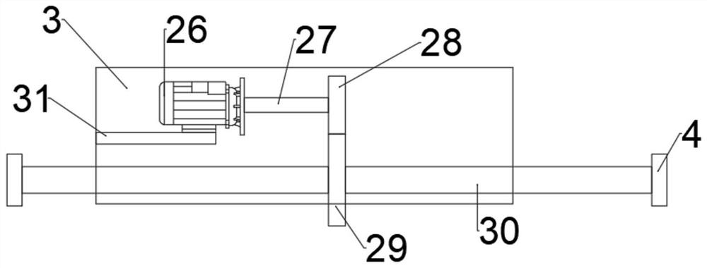
[0032]ReferFigure 1 ~ 3 A municipal sewage pipe cleaning device comprising a left connection block 2, and the upper and lower ends of the left connecting block 2 are slidably connected to the bottom plate 3, and the two bottom plate 3 is bolted with a first fixing plate 8, The first fixing plate 8 is connected to the connecting rod 6, and the two connecting rods 6 are connected between the two connecting rods 6, and the two bottom plate 3 is connected through the air spring 32, and the right side of the bottom plate 3 is slidable. The connection block 9, the right bolt of the right connection block 9 is connected to the cleaning mechanism, and the internal front side bolt of the bottom plate 3 is connected to the third fixing plate 31, and the upper bolt of the third fixing plate 31 is connected to the travel motor 26, the travel motor 26 The output terminal shaft is connected to the first row shaft 27. The first row shaft 27 is fixed from one end shaft of the traveling motor 26, an...

Embodiment 2

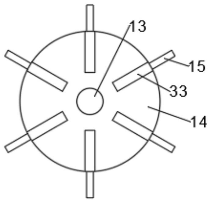
[0040]ReferFigure 4 ~ 5, A municipal sewage pipe cleaning device, this embodiment is provided with a slide groove 21 in the left side of the right connecting block 9, and the front and rear sides of the chute 21 are opened on both sides of the left side, and the bottom plate 3 is opened. The side bolt is connected to a sliding table 18. The front and rear side of the slide table 18 is bolted to connect the finite block 19, and the sliding stage 18 slides in the chute 21, the limit block 19 slides in the limit slot 20, using the slide table 18 and the chute 21 so that the bottom plate 3 is more stable when adapting to different sewage pipes, and the device is not operated when the device is not operating, and does not make the bottom plate 3 out of the right connection block when the device is not operating, using the limit block 19 and the restricted groove 20. 9, increasing its stability.

[0041]Working principle: Using the sliding table 18 and the chute 21 so that the bottom plate 3...


PUM


Abstract

The invention discloses a municipal sewage pipeline cleaning device, which comprises a left connecting block, bottom plates are arranged on the upper and lower ends of the right side of the left connecting block, and a first fixing plate is arranged on the side close to the two bottom plates, and the first fixing plate There is a connecting rod on the top, and the two connecting rods are connected by a connecting shaft. The middle part of the two bottom plates is connected by an air spring. The right connecting block is set on the right side of the bottom plate, and the cleaning mechanism is set on the right side of the right connecting block , the top of the third fixed plate is provided with a traveling motor. In the present invention, when the device is in operation, the walking motor is started to rotate the first walking shaft, so that the driving gear drives the driven gear to rotate, and the direct action of the connecting rod is used to make the running speeds of the two base plates the same. It is in the shape of chain teeth, which is more convenient when walking inside the sewage pipe, and will not cause the situation that the cleaning work cannot be carried out due to wheel slippage during the work project, and is suitable for mass promotion.

Description

Technical field[0001]The present invention relates to the field of cleaning techniques for sewage pipes, and more particularly to a municipal sewage pipe cleaning device.Background technique[0002]The sewage pipe system consists of a pipeline that collects and transports urban sewage and its attachment structures. The sewage flows into the dry tube by branch pipe, and then flows into the main tube, and finally flows into the sewage treatment plant. The pipeline is made of small to large, distributed similar rivers, which is a dendritic, and is completely different from the circulation of the water supply network. Sewage is generally the water surface difference between the pipes in the pipeline flows from the high direction, and there is no pressure inside the pipe, that is, the gravity flows.[0003]Urban underground drainage is an important system that prevents urban, drainage, and is only 600mm and 800mm in diameter for numerous bronchial drainage systems. Such a small pipeline is u...

Claims


Application Information

Patent Timeline
Patent Type & Authority Patents(China)
IPC IPC(8): E03F9/00
CPCE03F9/002
Inventor 孔金芳
Owner 四川九鼎建筑工程集团有限公司
Why Eureka
Try Eureka