
Mounting seat for communication equipment

A technology of communication equipment and mounting seat, which is applied in the direction of mechanical equipment, machine platform/bracket, supporting machine, etc. It can solve the problems of narrow pole spacing, affect the normal use of users, and cannot fix the RRU module, so as to avoid shear deformation Effect

Active Publication Date: 2021-10-19
HANGZHOU VOCATIONAL & TECHN COLLEGE
View PDF0 Cites 0 Cited by
  • Summary
  • Abstract
  • Description
  • Claims
  • Application Information

AI Technical Summary

Problems solved by technology

[0003] In the prior art, when the RRU module is installed on the pole, the pole is often combined with the machine frame. First, the pole is fastened to the pole, and then the machine frame is fixed on the pole. Finally, the The RRU module is inserted into the machine frame to complete the purpose of installing an RRU module on the pole. However, the distance between the RRU module and the pole is narrow, and the RRU module cannot be fixed well.
[0004] And as there are more and more centralized installation scenarios of communication equipment with multiple sectors and multiple frequency bands, this function cannot be realized by installing only one RRU module, which seriously affects the normal use of users, and RRUs are installed at different installation locations in an area The way of modules will bring a lot of inconvenience to the unified management and function division of RRU modules, and the workload of technicians is also relatively large during maintenance.

Method used


Image

  • Mounting seat for communication equipment
  • Mounting seat for communication equipment
  • Mounting seat for communication equipment

Examples


Embodiment Construction

[0035] In order to make the technical means, creative features, goals and effects achieved by the present invention easy to understand, the present invention will be further described below in conjunction with specific embodiments.

[0036] In the description of the present invention, it should be noted that the terms "upper", "lower", "inner", "outer", "front end", "rear end", "both ends", "one end", "another end" The orientation or positional relationship indicated by etc. is based on the orientation or positional relationship shown in the drawings, and is only for the convenience of describing the present invention and simplifying the description, rather than indicating or implying that the referred device or element must have a specific orientation, use a specific Azimuth configuration and operation, therefore, should not be construed as limiting the invention. In addition, the terms "first" and "second" are used for descriptive purposes only, and should not be understood ...


PUM


Abstract

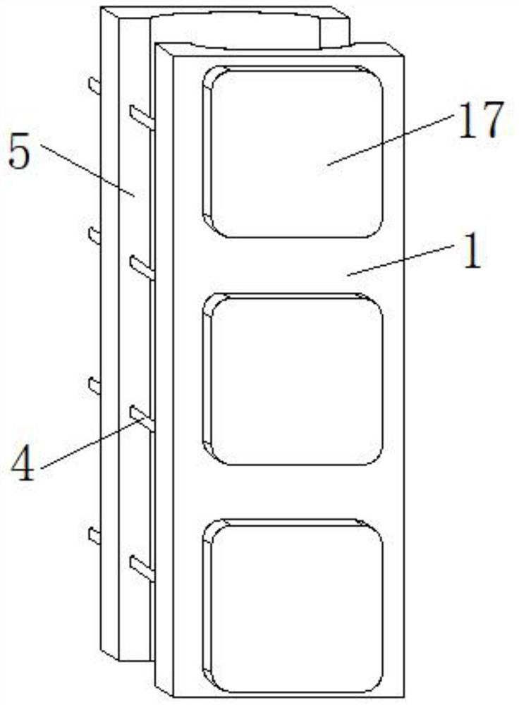
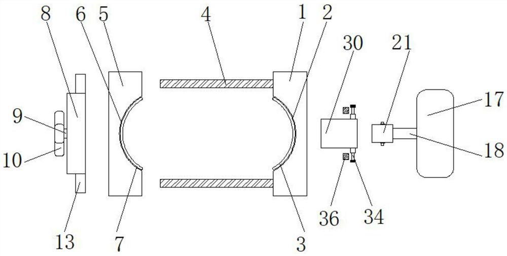
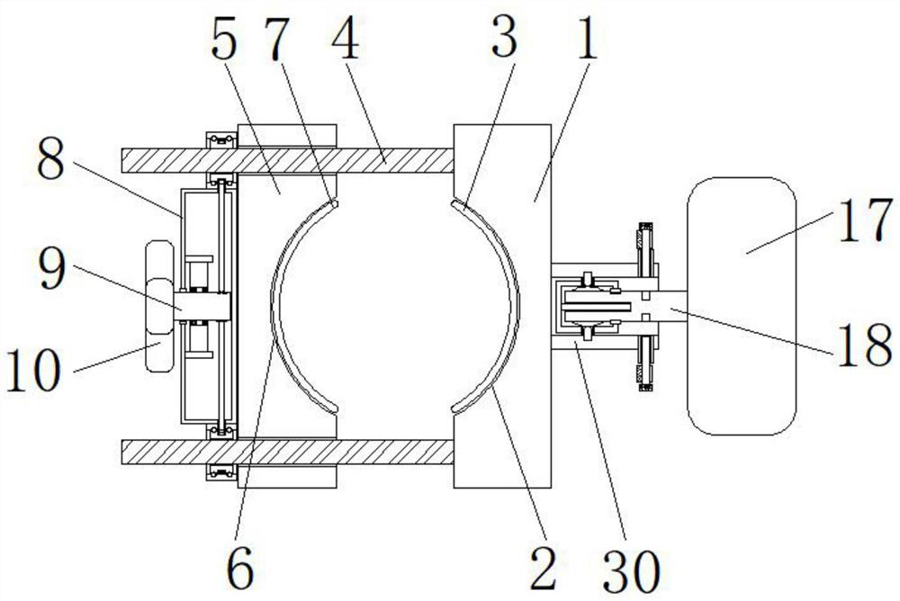
The invention discloses a communication equipment mounting seat, which comprises a mounting base. A first arc-shaped groove connecting the top and bottom of the mounting base is opened in the middle part on the left side of the mounting base. The inner wall on the right side of the first arc-shaped groove is fixedly connected with a second A buffer pad, the top and bottom of the left side of the mounting base are symmetrically fixedly connected with fixing studs, the left side of the mounting base is provided with a mounting pressure plate, and the middle part of the right side of the mounting plate is provided with a second arc-shaped groove connecting the top and bottom, The inner wall on the left side of the second arc-shaped groove is fixedly connected with a second buffer pad, the middle part on the left side of the installation pressure plate is provided with a bearing platform, the middle part on the left side of the bearing platform is provided with a rotating shaft, and the left end of the rotating shaft is fixedly connected with a rotating handle. The middle part of the shaft is sleeved with a mounting bracket, and the right end of the rotating shaft is sleeved with a gear. In the communication equipment installation seat of the present invention, a plurality of connecting columns, bosses, and bearings are provided on the right side of the installation base to facilitate centralized installation of RRU modules and provide convenience for maintenance.

Description

technical field [0001] The invention relates to the field of communication equipment, in particular to a communication equipment installation seat. Background technique [0002] Since the RRU remote radio unit module does not simultaneously amplify the noise when amplifying the signal, the RRU module is often used as a communication device in densely populated places such as residential quarters. In order to ensure the safety and stability of the RRU module during use, the RRU module is usually installed at a high position such as a pole, a wall or a signal tower. [0003] In the prior art, when the RRU module is installed on the pole, the pole is often combined with the machine frame. First, the pole is fastened to the pole, and then the machine frame is fixed on the pole. Finally, the The RRU module is inserted into the machine frame to complete the purpose of installing an RRU module on the pole. However, the distance between the RRU module and the pole is narrow, and th...

Claims


Application Information

Patent Timeline
Patent Type & Authority Patents(China)
IPC IPC(8): F16M13/02F16M11/04
CPCF16M11/041F16M13/022F16M2200/02
Inventor 孙丽潘承恩
Owner HANGZHOU VOCATIONAL & TECHN COLLEGE
Learn More