
High-voltage switch cabinet with protection function and using method thereof

A high-voltage switchgear and protective function technology, applied in the field of high-voltage switchgear, can solve the problems of separation between the unlocking action and the opening and closing action of the circuit breaker, and electric shock, so as to avoid the risk of electric shock and ensure the safety of personnel

Active Publication Date: 2020-09-15
HUAINAN WANTAI RONGBO LIGHTING TECH
View PDF6 Cites 2 Cited by
  • Summary
  • Abstract
  • Description
  • Claims
  • Application Information

AI Technical Summary

Problems solved by technology

[0006] (1) How to convert the rotary motion into a horizontal lateral motion through the connecting rod driver, so as to drive the latch and the first guide rod to move towards and away from each other, so as to solve the problem of separation of the locking and unlocking action of the cabinet door and the opening and closing action of the circuit breaker in the prior art question;
[0007] (2) How to use the cooperation of the compression spring, the second guide rod and the roller to solve the problem of the prior art that needs to be switched on before closing the cabinet door, resulting in potential safety hazards such as electric shock

Method used


Image

  • High-voltage switch cabinet with protection function and using method thereof
  • High-voltage switch cabinet with protection function and using method thereof
  • High-voltage switch cabinet with protection function and using method thereof

Examples


Embodiment Construction

[0032] The technical solutions of the present invention will be clearly and completely described below in conjunction with the embodiments. Apparently, the described embodiments are only some of the embodiments of the present invention, not all of them. Based on the embodiments of the present invention, all other embodiments obtained by persons of ordinary skill in the art without creative efforts fall within the protection scope of the present invention.

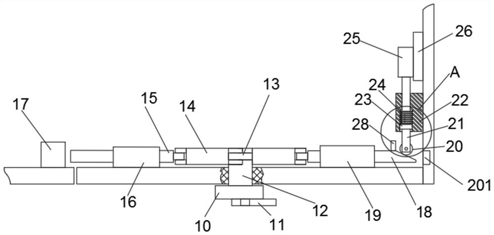
[0033] see Figure 1-5 As shown, a high-voltage switchgear with protective function includes a switchgear main body 1, an instrument observation window 2, a first cabinet door 3, a second cabinet door 4, a cabinet door handle 5, a fan 7, a warning light 9, and a rotating round table 10. Rotary handle 11, connecting round table 12, connecting rod driver 13, connecting rod 14, latch 15, latch sliding sleeve 16, latch seat 17, first guide rod 18, first guide rod sliding sleeve 19, roller 20, the first Two guide rods 21, secon...


PUM


Abstract

The invention discloses a high-voltage switch cabinet with a protection function and a using method of the high-voltage switch cabinet. The switch cabinet comprises a switch cabinet main body, a rotating handle, a connecting rod driving piece, a bolt, a bolt seat, a first guide rod, a roller, a second guide rod, a compression spring, a switch control piece and a roller limiting piece. A first cabinet door and a second cabinet door are installed on one side of the switch cabinet body through hinges. Cabinet door handles are fixed to the side face of the first cabinet door and the side face of the second cabinet door correspondingly. By rotating the rotating handle on the first cabinet door, the connecting rod driving piece is driven to rotate, the bolt is controlled to enter and exit from the bolt seat; the locking and unlocking of the switch cabinet door are realized; meanwhile, the unlocking is realized; the circuit switch is switched off through the cooperation of the first guide rod, the second guide rod and the roller, and the switch control part is driven by the compression spring and the second guide rod to switch on the circuit switch during locking, so that the risk of personnel electric shock caused by neglecting the closing operation of a circuit when a maintainer overhauls the interior of the switch cabinet is avoided, and the equipment safety and personnel safety are protected.

Description

technical field [0001] The invention relates to a switchgear structure, in particular to a high-voltage switchgear with protection function and its use method. Background technique [0002] The main function of the switchgear is to open and close, control and protect electrical equipment during the process of power generation, transmission, distribution and power conversion in the power system. The components in the switchgear mainly include circuit breakers, isolating switches, load switches, It is composed of operating mechanism, transformer and various protection devices. [0003] In the prior art, the maintenance personnel need to open the cabinet door and then disconnect the circuit switch before performing maintenance. The maintenance personnel sometimes forget to disconnect the circuit or make a wrong operation, which may cause electric shock hazards and major safety accidents. It is urgent to solve this situation. Protect. Therefore, we propose a high-voltage switc...

Claims


Application Information

Patent Timeline
IPC IPC(8): H02B1/30H02B1/54H02B1/56
CPCH02B1/30H02B1/54H02B1/565
Inventor 李建书陈静王龙陈大伟陈浩
Owner HUAINAN WANTAI RONGBO LIGHTING TECH
Learn More