Eureka AIR delivers breakthrough ideas for toughest innovation challenges, trusted by R&D personnel around the world.

Tattoo embroidering machine driven by linear motor

A linear motor and tattoo technology, applied in the field of tattoo embroidery machines, can solve the problems of motor noise, slow needle pushing speed, instability, etc., and achieve the effect of improving operating performance, reducing noise, and constant speed

Pending Publication Date: 2020-09-15
ONCE TOP MOTOR MFG
View PDF0 Cites 2 Cited by
  • Summary
  • Abstract
  • Description
  • Claims
  • Application Information

AI Technical Summary

Problems solved by technology

[0003] In the prior art, a rotary motor is used with an eccentric wheel conversion mechanism to convert, and the thrust shown in the process of pushing the needle is a hard thrust. It is not easy to grasp the depth of the sashimi during the operation, and there is a risk of stabbing and a tingling sensation; as The speed of the driving force motor is proportional to the power supply current. The control box of the tattoo embroidery machine provides a stable voltage signal, but the heat of the motor after operation will cause the resistance value of the motor to become higher, and the current of the motor will become smaller, so the tattoo embroidery push needle The speed will be slow or unstable; during the tattoo embroidery process, the mechanical conversion and the high-speed operation of the motor will generate a lot of noise, which will affect the comfort of the user during use.

Method used


Image

  • Tattoo embroidering machine driven by linear motor
  • Tattoo embroidering machine driven by linear motor
  • Tattoo embroidering machine driven by linear motor

Examples


Embodiment Construction

[0028] In order to make the object, technical solution and advantages of the present invention clearer, the present invention will be further described in detail below in conjunction with the accompanying drawings and embodiments. It should be understood that the specific embodiments described here are only used to explain the present invention, not to limit the present invention.

[0029] In the description of the present invention, it should be noted that the terms "center", "upper", "lower", "left", "right", "vertical", "horizontal", "inner", "outer" etc. The indicated orientation or positional relationship is based on the orientation or positional relationship shown in the drawings, and is only for the convenience of describing the present invention and simplifying the description, rather than indicating or implying that the referred device or element must have a specific orientation, or in a specific orientation. construction and operation, therefore, should not be constr...


PUM


Abstract

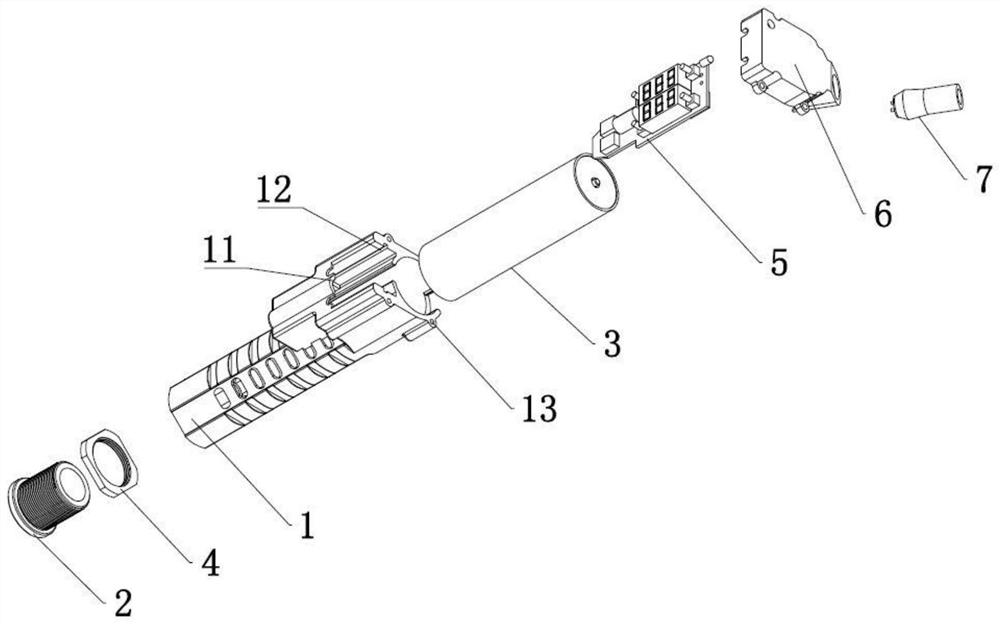
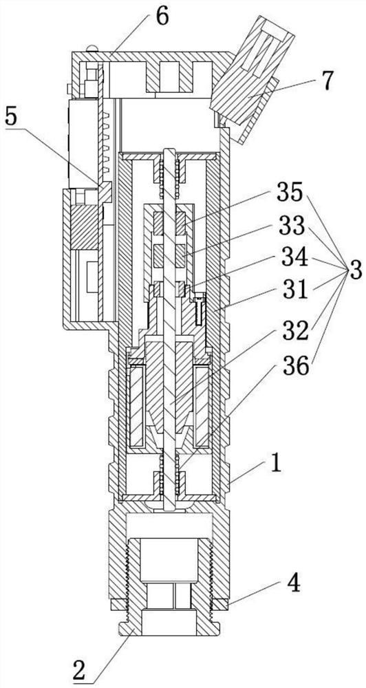
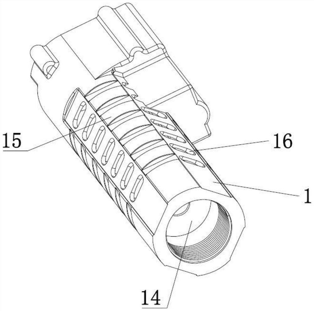
The invention relates to the technical field of tattoo embroidering machine driving, and discloses a tattoo embroidering machine driven by a linear motor. The tattoo embroidering machine comprises a machine shell, wherein a connector used for being externally connected with a tattoo embroidering needle is arranged at one end of the machine shell; the linear motor used for driving the external tattoo embroidering needle to move is arranged in the machine shell; the outer side of the connector is sleeved with a locking ring; a control circuit board used for controlling the working state of the linear motor is arranged on the machine shell; a machine cover is arranged at the other end, opposite to the connector, of the machine shell; and a power supply leading-in connector used for being externally connected with a power supply is arranged on the machine cover. The linear motor is used for driving the external tattoo embroidering needle to move, a mechanical conversion mechanism is not needed, and noise is greatly reduced; the stroke length of the linear motor pushing the needle is controlled through magnetic force, and the risk of stabbing and the stabbing pain feeling are avoided; the working state of the linear motor is controlled through the control circuit board, the speed of the needle and the stroke length of the needle can be adjusted at will, the speed is constant, and then the running performance of the tattoo embroidering machine is improved.

Description

technical field [0001] The invention relates to the technical field of tattoo embroidery machines, in particular to a tattoo embroidery machine driven by a linear motor. Background technique [0002] The beauty tattoo machines currently on the market use a rotary motor as the driving force, and then set the eccentric wheel to convert the front and rear linear motion of the ejector rod, and then push the needle to move suddenly; the machine used in the tattoo embroidery machine is set in the shape of a pen , easy to operate by hand, and the control circuit part of the tattoo embroidery machine is equipped with a separate control box. [0003] In the prior art, a rotary motor is used with an eccentric wheel conversion mechanism for conversion, and the thrust shown in the process of pushing the needle is a hard thrust. It is not easy to grasp the depth of the sashimi during the operation, and there is a risk of stabbing and a tingling sensation; as The speed of the driving mot...

Claims


Application Information

Patent Timeline
Patent Type & Authority Applications(China)
IPC IPC(8): A61M37/00H02K41/02
CPCA61M37/0076H02K41/02
Inventor 翁孟坤黄小军齐志虎
Owner ONCE TOP MOTOR MFG
Why Eureka
Eureka Blog
Learn More