
Mechanical control dental comprehensive treatment chair

A comprehensive treatment and dental technology, applied in the field of oral medicine, can solve the problems of restricting the service life of the treatment chair, the treatment chair cannot be used, and affect the treatment of patients, so as to achieve the effect of energy saving, service life, meeting the use demand and ensuring stability

Active Publication Date: 2020-09-15
西安交通大学口腔医院
View PDF12 Cites 0 Cited by
  • Summary
  • Abstract
  • Description
  • Claims
  • Application Information

AI Technical Summary

Problems solved by technology

[0004] The rotatable electro-hydraulic drive dental treatment chair disclosed in the above-mentioned prior art solution adopts electric control for its optional lifting and lowering. Therefore, in case of power failure or circuit failure or circuit damage, the treatment chair will be unusable, which greatly restricts the treatment. The service life of the chair, and because the circuit controls the treatment chair, once the work of the treatment chair breaks down, the treatment chair will automatically rotate during the treatment process, which will directly affect the treatment of the patient, and even cause secondary damage to the patient in severe cases

Method used


Image

  • Mechanical control dental comprehensive treatment chair
  • Mechanical control dental comprehensive treatment chair
  • Mechanical control dental comprehensive treatment chair

Examples


Embodiment Construction

[0035] The present invention will be described in further detail below in conjunction with the accompanying drawings.

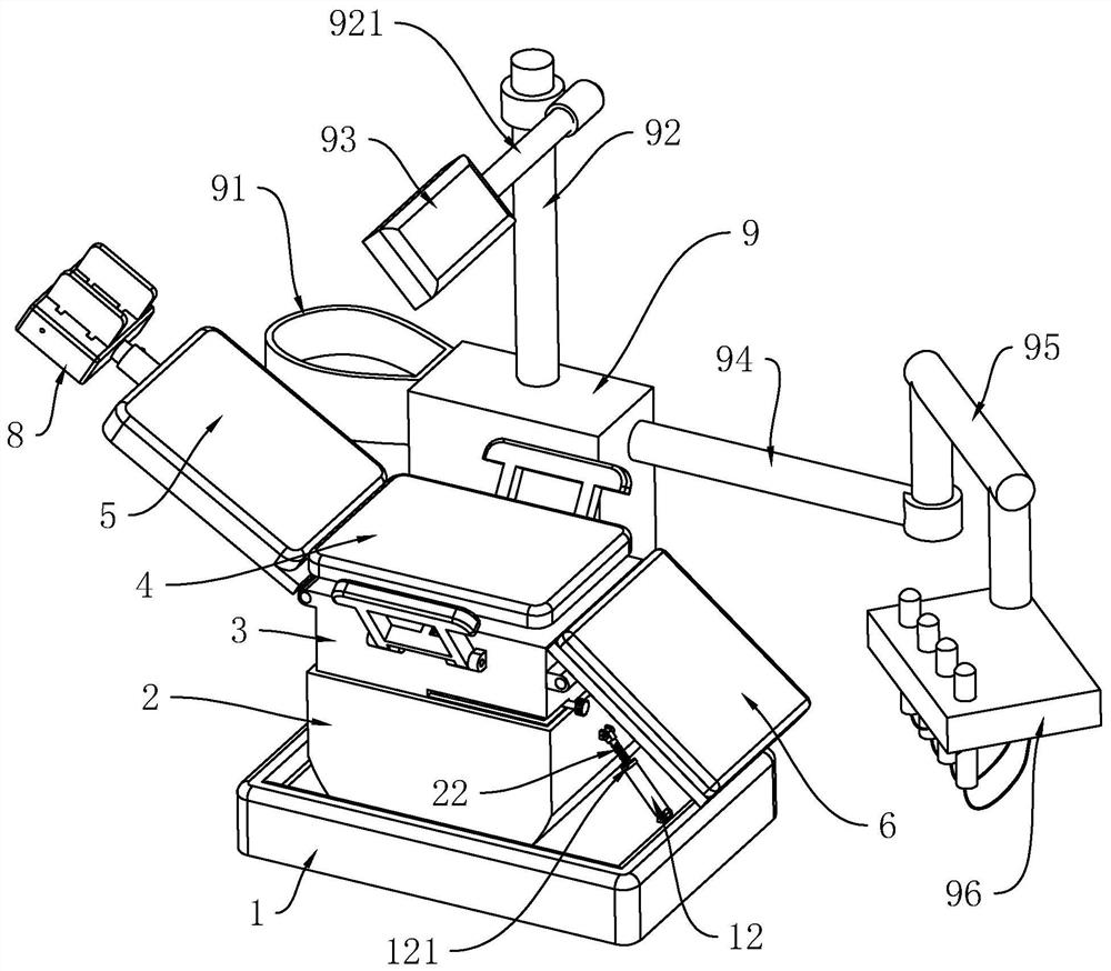
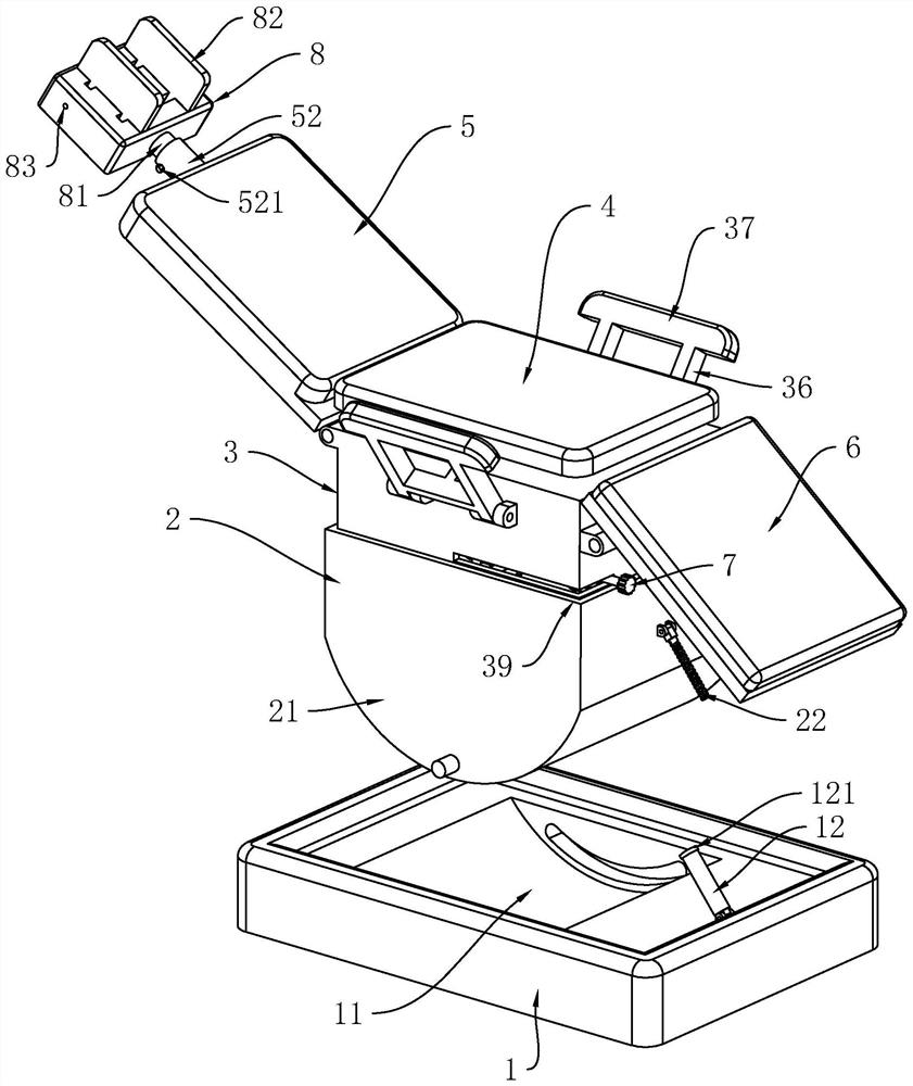
[0036] refer to figure 1 and figure 2 , is a mechanically regulated comprehensive dental treatment chair disclosed by the present invention, comprising a base 1 arranged horizontally, an underframe 2 is arranged on the upper side of the base 1, and an arc-shaped sliding block 21 is fixedly connected to the underside of the underframe 2. The axial direction of the arc-shaped slider 21 is perpendicular to the length direction of the base 1, the upper side of the base 1 is provided with an arc-shaped chute 11, the axis direction of the arc-shaped chute 11 is perpendicular to the length direction of the base 1, and the arc-shaped slider 21 slides Move and connect in the arc-shaped chute 11, so that the underframe 2 can be rotated. One end of the base 1 corresponding to the arc-shaped chute 11 is hinged with a swing column 12, and the swing column 12 can rotate ...


PUM


Abstract

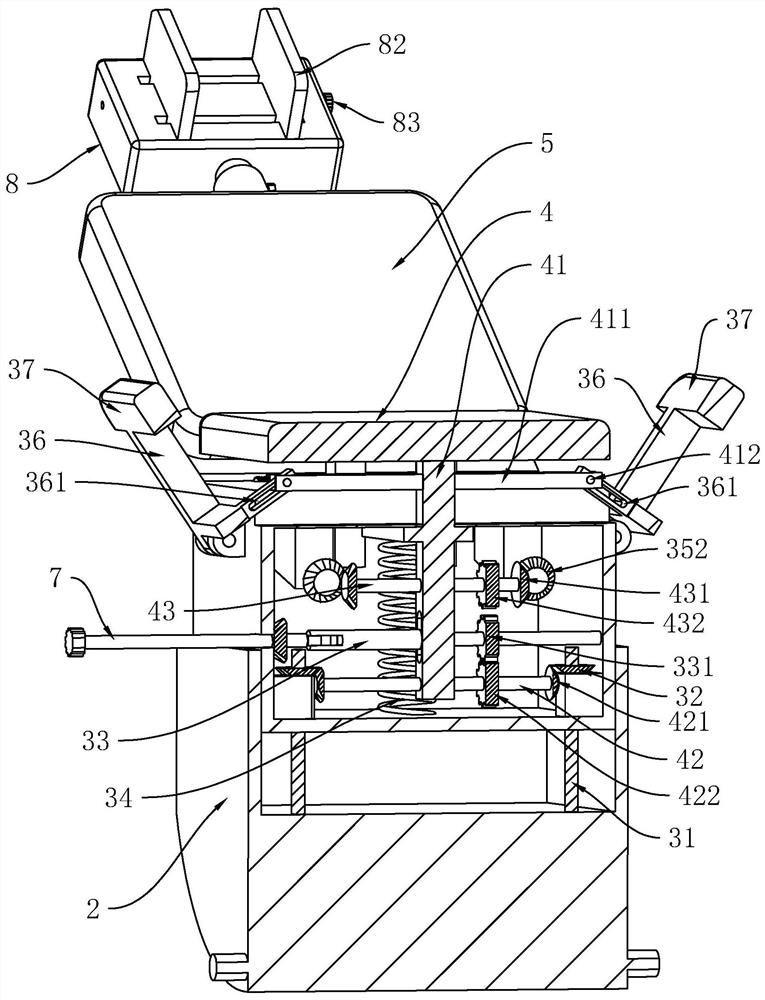
The invention relates to the technical field of oral medical treatment, in particular to a mechanical control dental comprehensive treatment chair. The mechanical control dental comprehensive treatment chair comprises a bottom frame; a seat frame is slidably connected to the upper side of the bottom frame; lifting screws are slidably arranged on the two sides of the seat frame; the lower ends of the lifting screws are fixedly connected to the bottom frame; bevel gears I with the middles in threaded connection with the lifting screws are rotationally connected to the two sides of the seat frame; a driving shaft is rotationally connected to the interior of the seat frame; a driving gear I is fixedly connected to the driving shaft; a seat plate is slidably connected to the upper side of the seat frame; a fixed frame is fixedly connected to the lower side of the seat plate; a movable shaft I is rotationally connected to the lower end of the fixed frame; bevel gears II are fixedly connectedto the two ends of the movable shaft I; a driving gear II is fixedly connected to the movable shaft I; and the seat frame is fixedly connected with a push spring which can push the fixed frame to move upwards until the bevel gears II are meshed with the bevel gears I in a normal state and meanwhile drives the driving gear II to be meshed with the driving gear I. The treatment chair has the effects that the structure of the treatment chair can be conveniently adjusted without electric power, and on the other hand, the stability of the treatment chair during working can be ensured.

Description

technical field [0001] The invention relates to the technical field of oral medicine, in particular to a mechanically regulated dental comprehensive treatment chair. Background technique [0002] The mechanically regulated dental comprehensive treatment chair is an essential medical device for stomatologists, and is used for oral surgery and oral disease inspection and treatment. [0003] The existing reference application announcement number is: Chinese invention patent of CN107928963A, which discloses a rotatable electro-hydraulic drive dental treatment chair, including a base, the base is fixedly installed on the ground, and a rotating mechanism is arranged above the base , an electro-hydraulic lifting device is provided above the rotating head, a backrest is hinged at the top of the seat, a headrest is fixedly connected to the top of the backrest through a connecting piece, and a support that matches the seat is provided on the side of the base The support frame is fixe...

Claims


Application Information

Patent Timeline
IPC IPC(8): A61G15/02A61G15/10A61G15/12
CPCA61G15/02A61G15/10A61G15/12A61G15/125
Inventor 高江红朱春晖黄瑞哲
Owner 西安交通大学口腔医院
Learn More