
Method for positioning nerve regulating and controlling target region

A positioning method and target area technology, applied in medical science, telemetry patient monitoring, sensors, etc., can solve the problems of cumbersome operation, inability to accurately display the target area, and lack of effective devices for neuroregulation brain target area positioning

Active Publication Date: 2020-09-15
WEST CHINA HOSPITAL SICHUAN UNIV
View PDF9 Cites 7 Cited by
  • Summary
  • Abstract
  • Description
  • Claims
  • Application Information

AI Technical Summary

Problems solved by technology

[0002] For a long time, there has been a lack of effective devices for the positioning of neuromodulation brain targets. In recent years, optical navigation devices have been used to calibrate the control devices to brain structure images using traceable light balls because of high cost (optical navigation cameras imported from abroad are commonly used) and cumbersome operations (need to pass calibration The indicator points to the characteristic structure points of the head to complete the calibration), and cannot adapt to head movement and cannot accurately display the target area, so it is rarely used in clinical applications

Method used


Image

  • Method for positioning nerve regulating and controlling target region
  • Method for positioning nerve regulating and controlling target region

Examples


Embodiment Construction

[0026] In order to make the object, technical solution and advantages of the present invention clearer, the present invention will be further described in detail below in conjunction with the accompanying drawings.

[0027] A method for locating a neuromodulation target region, comprising the following steps:

[0028] Step s1:

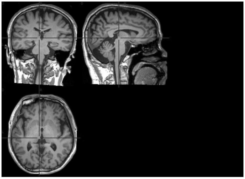
[0029] Obtain the magnetic resonance functional image and magnetic resonance structural image of the patient through magnetic resonance, and then obtain the target area.

[0030] In step s1, there are 3 methods to obtain the target area, namely:

[0031] Method a: Obtain brain structure images through magnetic resonance, and select target areas according to brain structure partitions;

[0032] Method b: Obtain the activation area of ​​the brain from the task state fMRI, and use the activation area or the associated area of ​​the activation area as the target area;

[0033] Method c: Through the correlation calculation of the voxel signal of the rest...


PUM


Abstract

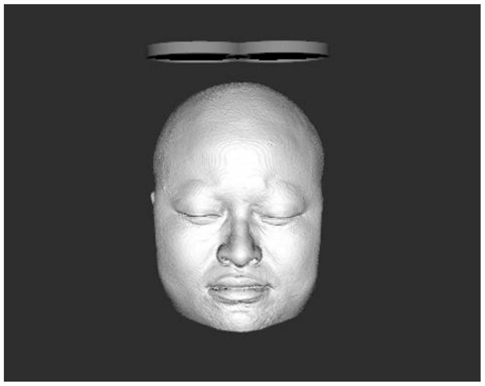
The invention discloses a method for positioning a nerve regulating and controlling target region. The method comprises the following steps: s1: acquiring a magnetic resonance functional image and a magnetic resonance structural image of a sufferer through magnetic resonance, so as to obtain a target region; S2: registering the magnetic resonance functional image acquired in the s1 to the magneticresonance structural image by adopting a main axis method, so as to obtain a target region from the magnetic resonance structural image; S3: acquiring three-dimensional coordinates of face characteristic points of a head profile diagram of the sufferer; S4: subjecting the three-dimensional coordinates to three-dimensional registration with the face characteristic points of the head profile diagram of the sufferer obtained through a depth camera; S5: identifying and positioning a regulating and controlling device through the depth camera, wherein the regulating and controlling device is a transcranial magnetic stimulation coil TMS or ultrasonic regulating and controlling transducer array; and S6: completing positioning. According to the method, the regulating and controlling target regioncan be positioned through the regulating and controlling device under the condition that indicator calibration is not carried out and a position of the regulating and controlling device, for example the TMS, relative to the target region can be directly viewed.

Description

technical field [0001] The invention relates to the technical field of computer images, in particular to a positioning method of a neural regulation target area. Background technique [0002] For a long time, there has been a lack of effective devices for the positioning of brain target areas for neural regulation. In recent years, optical navigation devices have been used to calibrate the control device to brain structure images using traceable photospheres because of high cost (optical navigation cameras imported from abroad are commonly used) and cumbersome operations (need to pass calibration The indicator points to the characteristic structure points of the head to complete the calibration), and it cannot adapt to head movement and cannot accurately display the target area, so it is rarely used in clinical applications. Contents of the invention [0003] The purpose of the present invention is to provide a method for positioning the target area of ​​the control device...

Claims


Application Information

Patent Timeline
Patent Type & Authority Applications(China)
IPC IPC(8): A61B5/055A61B5/00
CPCA61B5/055A61B5/0042A61B5/746A61B2576/026
Inventor 龚启勇幸浩洋黄晓琦吕粟孙怀强
Owner WEST CHINA HOSPITAL SICHUAN UNIV
Learn More