
Probe control method and probe control device

A control method and data control technology, applied in the field of medical devices, can solve problems such as increased surgical risk, operation failure, and device damage, and achieve the effects of saving manpower and material costs, improving efficiency and accuracy, and simple control methods

Active Publication Date: 2021-08-31
BEIJING DITAN HOSPITAL CAPITAL MEDICAL UNIV
View PDF7 Cites 0 Cited by
  • Summary
  • Abstract
  • Description
  • Claims
  • Application Information

AI Technical Summary

Problems solved by technology

[0005] For the above-mentioned laparoscopes, it is generally difficult for the hand holding the mirror to accurately judge the operator's intention, resulting in the visual field being unable to keep up with the operator's thinking, poor operation cooperation, and increased operation risk
For the above-mentioned soft detection lens, since the detection space orientation can be very complicated, such as in the intestinal tract or inside the engine, the operator must undergo a lot of training to become familiar with it; Injury, equipment damage and other adverse consequences

Method used


Image

  • Probe control method and probe control device
  • Probe control method and probe control device
  • Probe control method and probe control device

Examples


Embodiment 1

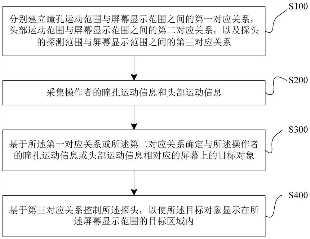
[0062] see figure 1 , the present embodiment provides a probe control method, comprising the following steps:

[0063] S100: respectively establish a first correspondence between the pupil movement range and the screen display range, a second correspondence between the head movement range and the screen display range, and a third correspondence between the probe detection range and the screen display range relation.

[0064] The pupil movement range in this embodiment may be the position coordinates of the pupil in the orbital area. It can be understood that the pupil movement range is within the orbital area of ​​the operator, and the screen display range is within the physical area of ​​the screen. The operator looks at different pixels within the display range of the screen through the movement of the pupils. By one-to-one correspondence between the coordinates of the operator's pupil in the orbital area and the coordinates of one or some pixels on the screen in the scre...

Embodiment 2

[0111] This embodiment proposes a probe control device 80, such as Figure 8 As shown, it includes an information collection module 81 , a target determination module 82 and a control module 83 . in:

[0112] An information collection module 81, configured to collect movement information of the monitored parts of the operator;

[0113] A target determination module 82, configured to determine a target object corresponding to the motion information on the screen based on the preset correspondence between the motion range of the monitored part and the screen display range;

[0114] The control module 83 is configured to generate control data or control instructions carrying the control data based on the third preset correspondence between the detection range of the probe and the screen display range, and the control data or the control instructions are used to control The probe moves.

[0115] The probe control device proposed by the present invention allows the operator to p...


PUM


Abstract

The invention discloses a probe control method and a probe control device. The method includes the following steps: collecting movement information of the monitored part of the operator; based on a preset correspondence between the movement range of the monitored part and the screen display range, determining the corresponding movement information on the screen the target object; based on the third preset corresponding relationship between the detection range of the probe and the screen display range, control data or a control instruction carrying the control data is generated, and the control data or the control instruction is used to control the Probe action. Through the present invention, the operator can precisely control the content displayed on the screen only through his own pupil movement and head movement, without the assistance of a third person, which improves the efficiency and accuracy of probe control.

Description

technical field [0001] The invention relates to the technical field of medical devices, in particular to a probe control method and a probe control device. Background technique [0002] The probe is the repackaging form of the sensor. According to its basic sensing function, the probe can be divided into thermal probe, light sensitive probe, gas sensitive probe, force sensitive probe, magnetic sensitive probe, moisture sensitive probe, sound sensitive probe, radiation sensitive probe, color sensitive probe, Sensitive probes and taste sensitive probes, video probes and other categories. Among them, video probes and ultrasonic probes have been widely used in the medical field in recent years. [0003] Take the example of a laparoscope in a video probe. Laparoscopic surgery is performed by at least one surgeon and one hand-held mirror. Among them, the long-rod lens of the laparoscope is inserted into the abdominal cavity through a cannula inserted on the abdominal wall, and ...

Claims


Application Information

Patent Timeline
Patent Type & Authority Patents(China)
IPC IPC(8): A61B1/313A61B1/00A61B1/045A61B90/00G06F3/01
CPCA61B1/00006A61B1/00009A61B1/00043A61B1/00163A61B1/045A61B1/3132A61B90/36A61B2090/364G06F3/012G06F3/013
Inventor 高越鲁岩胡翀
Owner BEIJING DITAN HOSPITAL CAPITAL MEDICAL UNIV
Learn More