Multi-drill rod linkage driving-type soil digging vehicle
A linkage-driven, multi-drilling rod technology, applied in planting methods, excavation/covering trenches, applications, etc., can solve the problems of high labor intensity, difficult to drill down, low labor efficiency, etc., to improve crushing efficiency, The effect of improving the speed of digging and improving the efficiency of destruction
- Summary
- Abstract
- Description
- Claims
- Application Information
AI Technical Summary
Problems solved by technology
Method used
Image
Examples
Embodiment 1
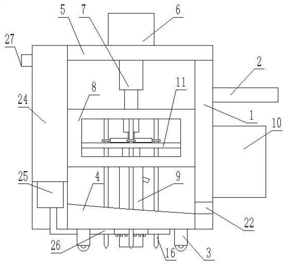
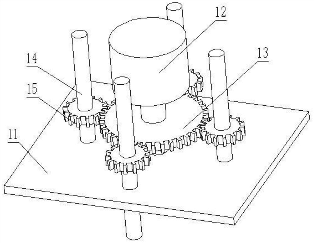
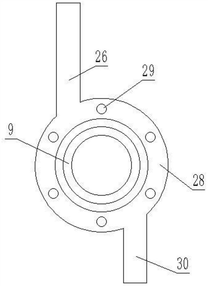
[0020] see Figure 1-4 , a multi-drill rod linkage driven soil digging vehicle, including a car body composed of a top plate 5, a vertical frame 1 and a bottom plate 4 sequentially docked, and a control box 10 and an operating rod 2 are arranged on the outside of the vertical frame 1, and the operating rod 2 Located above the control box 10, a control panel and a storage battery are provided in the control box 10, a switch connected to the control panel is provided on the operating rod 2, and a mobile support wheel 3 is provided at the bottom of the bottom plate 4, which can be used by the operating rod during use. 2 Push the car body to move to the position where the pit needs to be dug, and then fix the car body for work; the inner side of the vertical frame 1 is provided with a drive box 8, and the drive box 8 is slidingly connected with the vertical frame 1, and a hydraulic cylinder is fixed in the center of the top surface of the top plate 5 6. The output end of the hydra...
Embodiment 2
[0025] refer to Figure 5 , on the basis of Embodiment 1, in order to ensure that the drive box 8 will not be damaged by shaking and offset when sliding along the vertical frame 1, the vertical frame 1 is provided with a vertical chute 20, and the sliding The groove 20 is in the shape of a "T" in cross section, and a slider located in the chute 20 and slidably connected with the chute 20 is provided on the outer wall of the drive box 8. The cross section of the slider is in a "T" shape matching the chute 20, Through the cooperation of the slider and the chute 20, the stability of the lifting of the drive box 8 can be ensured.
[0026] Further, two vertical balance grooves 21 are also provided on the vertical frame 1, and the two balance grooves 21 are located on both sides of the chute 20, and the outer wall of the drive box 8 is provided with a balance groove inserted into the balance groove 21 and connected with the balance groove. 21 slidingly connected balance weights, thre...
PUM
 Abstract
Description
Claims
Application Information
 - Generate Ideas
- Intellectual Property
- Life Sciences
- Materials
- Tech Scout
- Unparalleled Data Quality
- Higher Quality Content
- 60% Fewer Hallucinations
Browse by: Latest US Patents, China's latest patents, Technical Efficacy Thesaurus, Application Domain, Technology Topic, Popular Technical Reports.
© 2025 PatSnap. All rights reserved.Legal|Privacy policy|Modern Slavery Act Transparency Statement|Sitemap|About US| Contact US: help@patsnap.com


