


Quick Research
Generate reliable direction feasibility study reports for your R&D in just a few steps.

Technical Q&A
Discover and master advanced knowledge NOW. Basics, ideas, possibilities, all at once.

Find Solutions
As an expert in R&D theories, this can generate solutions to your technical problems instantly.

Evaluate Feasibility
Analyze your overall solution with one click, know your potential R&D risks in advance.

Monitor Landscape
Get weekly tech updates, stay abreast of the latest tech innovations and key insights.
Corn threshing device
A corn threshing and charging mechanism technology, applied in threshing equipment, agricultural machinery and equipment, energy-saving measures, etc., can solve the problems of large workload, high cost, easy blockage, etc., and achieve the effect of energy saving, simple structure and convenient operation.
- Summary
- Abstract
- Description
- Claims
- Application Information
AI Technical Summary
Problems solved by technology
Method used
Image

Examples
Embodiment 1
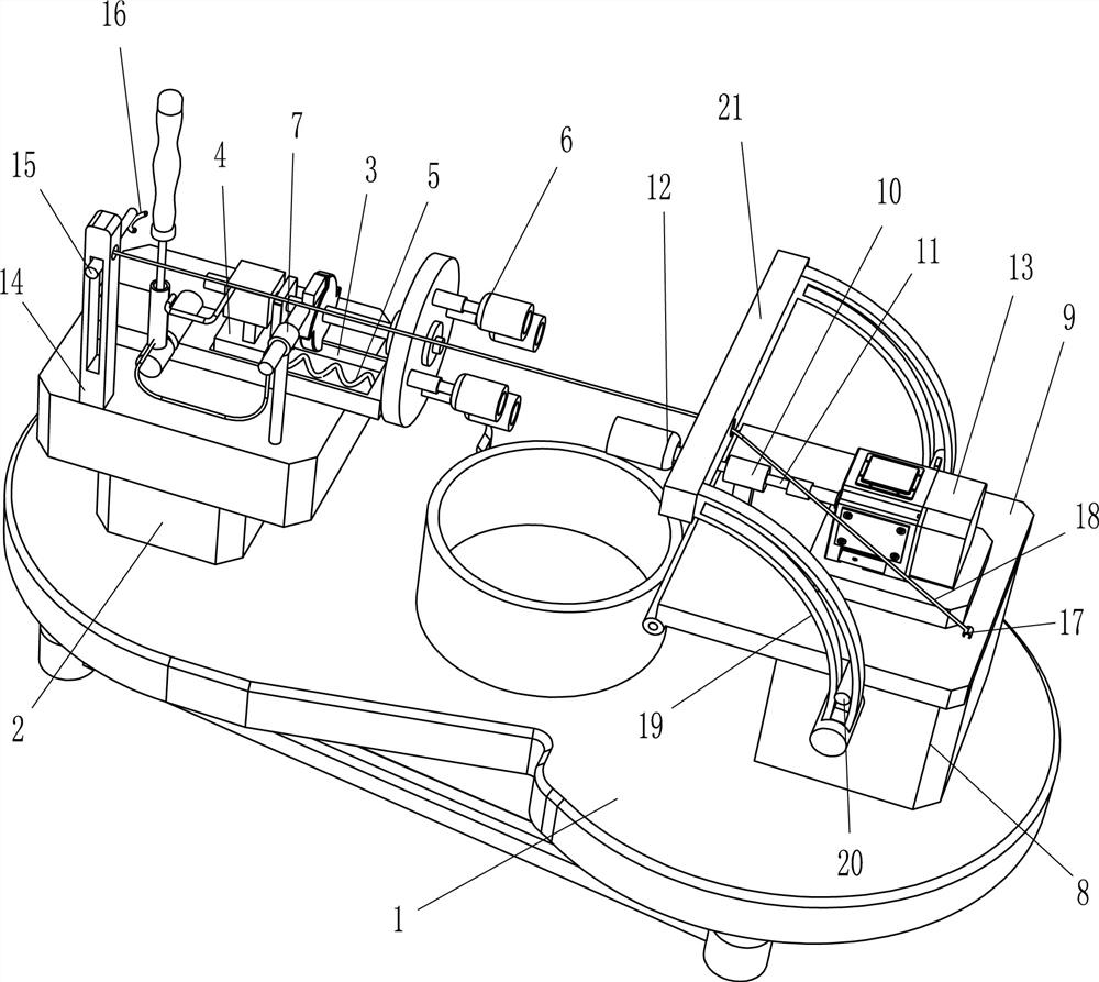
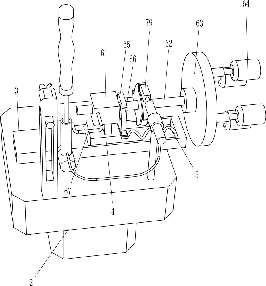
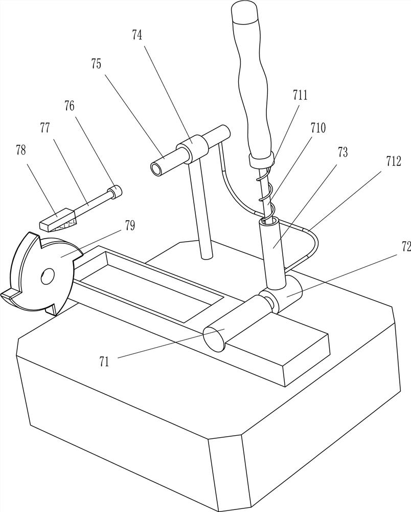
[0020] Such as Figure 1-3 As shown, a corn threshing device includes a base 1, a workbench 2, a straight slide rail 3, a straight slide block 4, a first elastic member 5, a charging mechanism 6, a reversing mechanism 7, a fixing seat 8, and a turning plate 9. The second bearing seat 10, the second rotating shaft 11, the threshing sleeve 12 and the servo motor 13, the workbench 2 is arranged on the left side of the top of the base 1, and the straight slide rail 3 is arranged on the workbench 2, and the straight slide rail 3 slides The straight-running slider 4 is provided with a straight-running slider 4, and a first elastic member 5 is arranged between the straight-running slider 4 and the right side wall of the straight-running slide rail 3. The first elastic member 5 is a compression spring, and the straight-running slider 4 is provided with a charging Mechanism 6, the workbench 2 is provided with a reversing mechanism 7 for adjusting the angle of the charging mechanism 6, ...
Embodiment 2
[0025] On the basis of Example 1, such as figure 1 As shown, it also includes a straight guide rail 14, a sliding shaft 15, an arc guide plate 16, a fixed block 17 and a stay cord 18. Axle 15, sliding shaft 15 rear ends are provided with arc-shaped guide plate 16, and arc-shaped guide plate 16 cooperates with handle 710, and fixed block 8 top right side is provided with fixed block 17, and fixed block 17 is provided with stay cord 18, and stay cord 18 is other One end passes through the small hole of the straight guide rail 14 and is connected with the slide shaft 15 .
[0026] When the staff completes a corn threshing operation and drives the handle 710 to reset, the staff turns the handle 710 to the left, and the handle 710 squeezes the arc guide plate 16, and the arc guide plate 16 drives the sliding shaft 15 to move downward in the straight guide rail 14. The shaft 15 drives the turnover plate 9 to be pulled up through the pull rope 18, and then the threshing sleeve 12 is...
PUM
 Abstract
Description
Claims
Application Information
 - R&D Engineer
- R&D Manager
- IP Professional
- Industry Leading Data Capabilities
- Powerful AI technology
- Patent DNA Extraction
Browse by: Latest US Patents, China's latest patents, Technical Efficacy Thesaurus, Application Domain, Technology Topic, Popular Technical Reports.
© 2024 PatSnap. All rights reserved.Legal|Privacy policy|Modern Slavery Act Transparency Statement|Sitemap|About US| Contact US: help@patsnap.com