
Anti-shaking pay-off rack used for electric power construction

An electric construction, anti-shake technology, applied in the direction of conveying filamentous materials, thin material handling, transportation and packaging, etc., can solve the problems of large vibration of cables, inconvenient control of wire rollers, and single structure of pay-off racks, etc. Achieve the effect of reducing large-scale jitter, reducing hard friction, and reducing operating intensity

Inactive Publication Date: 2020-09-08
高焕根
View PDF15 Cites 1 Cited by
  • Summary
  • Abstract
  • Description
  • Claims
  • Application Information

AI Technical Summary

Problems solved by technology

[0003] However, there are some shortcomings in the pay-off racks for electric power construction in the market. The traditional pay-off racks have a single structure. During the pay-out process, the cables are prone to large vibrations, which increases the operating intensity of the staff. And in the process of unwinding, it is inconvenient to control the wire roller

Method used


Image

  • Anti-shaking pay-off rack used for electric power construction
  • Anti-shaking pay-off rack used for electric power construction
  • Anti-shaking pay-off rack used for electric power construction

Examples


Embodiment Construction

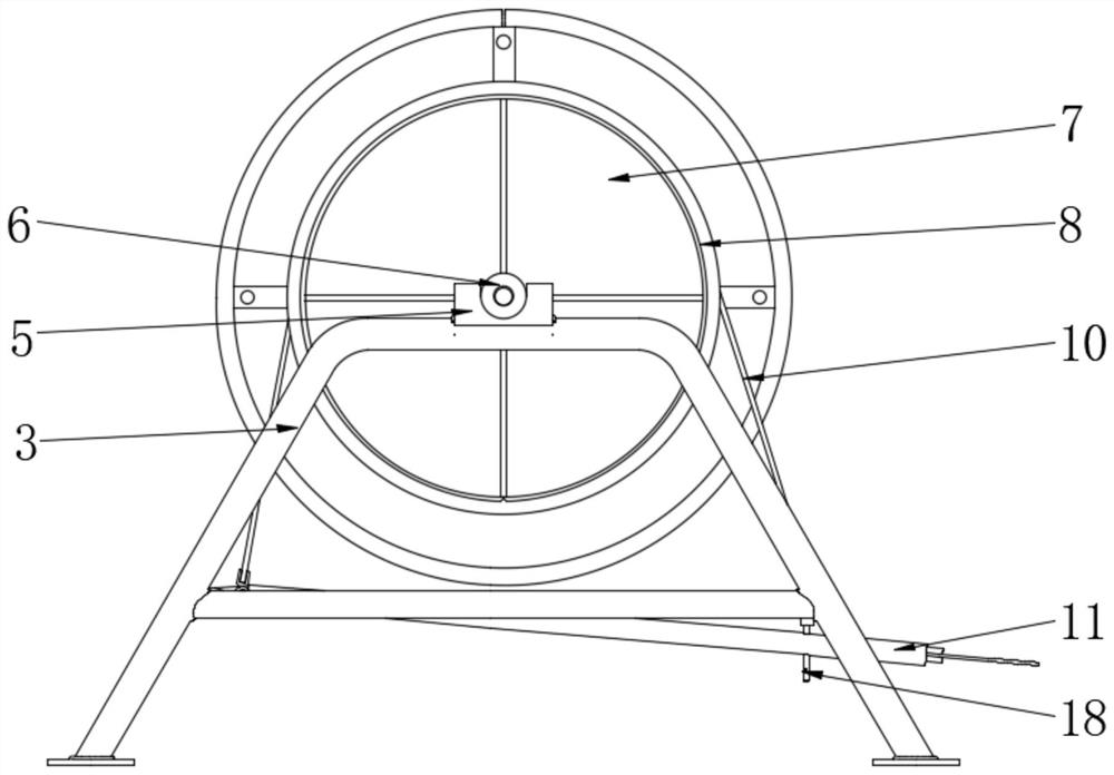
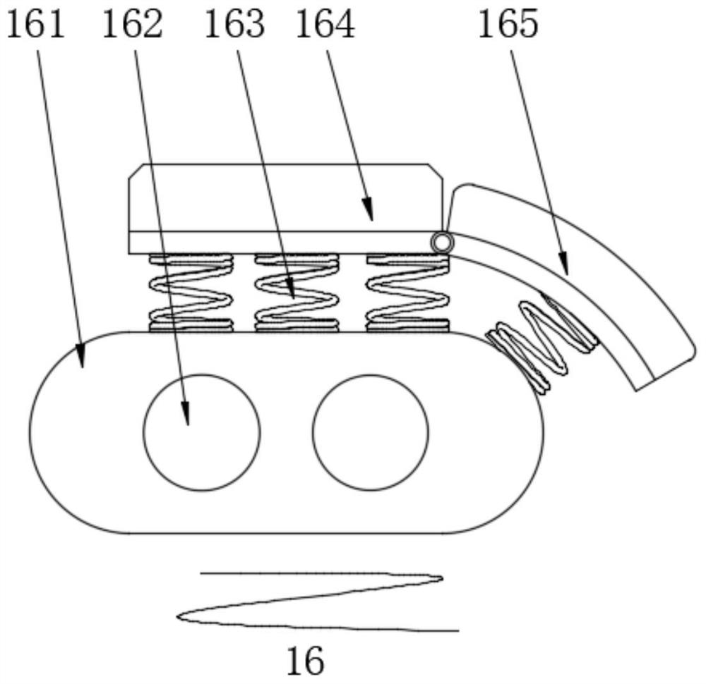
[0019] see Figure 1~3 , in an embodiment of the present invention, an anti-shake type pay-off frame for electric power construction, including a support base 1, a universal wheel 2 is rotatably connected to the bottom of the support base 1, and the top of the support base 1 is located on a A push handle 4 is fixed at the side position, and a support mechanism is fixed on one side of the push handle 4 above the support chassis 1. The support mechanism includes a positioning bracket 3 fixed at a position above the support chassis 1, and the top of the positioning bracket 3 is located in the middle position. Positioning ferrules 5 are symmetrically fixed at the center, and the inner side of the positioning bracket 3 is located at the bottom position to rotate and connect with a pedal rod 11, and the top of the pedal rod 11 is connected with a stop bandage 10, and the stop bandage 10 is made of braided material. , the line roller 7 is socketed with the stop bandage 10 through the...


PUM

PropertyMeasurementUnit
Lengthaaaaaaaaaa

Abstract

The invention relates to the technical field of electric power construction, and discloses an anti-shaking pay-off rack used for electric power construction. In order to improve cable pay-off stability in the electric power construction, a supporting mechanism is fixed on one side of a pushing handle above a supporting bottom frame; a wire roller is clamped with a positioning clamping cover through a bearing pedestal; the inner side of a positioning foundation bed is symmetrically fixedly provided with a spacing sliding rod; and the outer side of each spacing sliding rod is clamped with a down-pulling sliding seat and an up-pulling sliding seat in sequence from front to back. Through the supporting of the supporting mechanism for the wire roller, a worker can conveniently carry out installing, fetching and placing work of the wire roller, meanwhile, a position stopping bandage on the inner side of the supporting mechanism is used for sheathing the wire roller, so that the worker can conveniently control a wire roller pay-off speed, through the combination of the down-pulling sliding seat and the up-pulling sliding seat, a situation that the cable shakes to a large extent due to rigid pulling in a pay-off process can be lowered, and therefore, the operation intensity of the worker is lowered.

Description

technical field [0001] The invention relates to the technical field of electric power construction, in particular to an anti-shake pay-off frame for electric power construction. Background technique [0002] As a common device for electric power construction, pay-off racks can be divided into active pay-off racks and passive pay-off racks according to power transmission, and can be divided into vertical pay-off racks and horizontal pay-off racks according to the axis mode. It can be divided into: shaft-type pay-off rack and shaft-less pay-off rack, among which the vertical pay-off rack is a more commonly used pay-off equipment. [0003] However, there are some shortcomings in the pay-off racks for electric power construction in the market. The traditional pay-off racks have a single structure. During the pay-out process, the cables are prone to large vibrations, which increases the operating intensity of the staff. And in the process of unwinding, it is inconvenient for the...

Claims


Application Information

Patent Timeline
IPC IPC(8): B65H49/30B65H67/02B65H59/04B65H59/06
CPCB65H49/30B65H59/04B65H59/06B65H67/02B65H2701/34
Inventor 高焕根
Owner 高焕根
Learn More