Medical mask
A mask and cover technology, applied in the field of medical supplies, can solve the problems of single structure, difficulty in breathing for users, and difficulty in inhaling, and achieve the effects of being convenient and simple to use, avoiding difficulty in inhaling, and having a wide range of applications.
- Summary
- Abstract
- Description
- Claims
- Application Information
AI Technical Summary
Problems solved by technology
Method used
Image
Examples
Embodiment 1
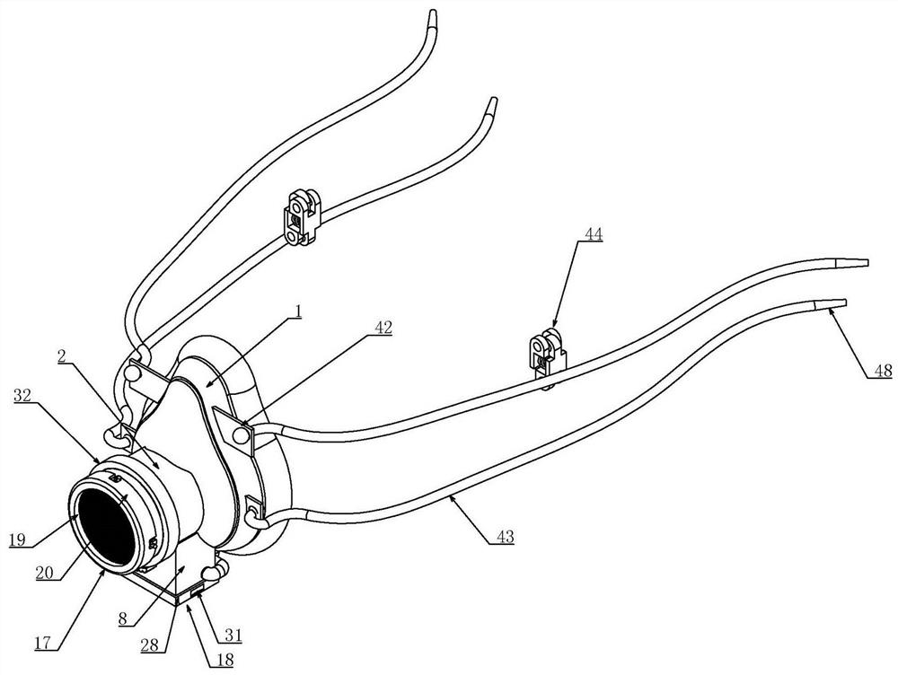
[0037] Embodiment one, combined with the attached Figure 1-18, a medical mask, comprising a transparent mask body 1, the transparent mask body 1 can see the breathing situation inside the mask body 1 from the outside, it is characterized in that the front end of the mask body 1 communicates with a cylinder 2, the circular cylinder 2 Both ends of the cylinder 2 are open, and a vertical partition 3 is connected inside the cover body 1 to divide the inside of the cover body 1 into two chambers, the front chamber 4 and the rear chamber 5, respectively. The front chamber 4 communicates with the cylinder 2, the rear chamber 5 fits the face of the user, and the rear end of the partition 3 is connected to a horizontally arranged baffle 6 to divide the rear chamber 5 There are two upper and lower layers, and there are multiple groups of first gas one-way valves 7 used to flow gas from the front side chamber 4 to the back side chamber 5 connected to the partition plate 3, and the first...
Embodiment 2
[0040] Embodiment two, on the basis of embodiment one, in conjunction with the attached Figure 1-18 , the filter screen replacement structure 17 includes an annular blocking plate 20, the middle part of which is open in the shape of an annular structure, and the blocking plate 20 is provided with an annular groove matching the cylinder 2 21, satisfying that the blocking plate 20 can be set on the cylinder 2 through the annular groove 21, and the end of the cylinder 2 is inserted into the annular groove 21 to realize the fitting effect between the blocking plate 20 and the cylinder 2. The annular groove 21 is axially slid to fit an annular transition plate 22, the size of the transition plate 22 just matches the size of the annular groove 21, and a set of springs set in the annular groove 21 is connected between the bottom of the annular groove 21 and the transition plate 22 23. The outer circumference of the cylinder 2 is uniformly connected with multiple groups of bayonet pi...
Embodiment 3
[0041] Embodiment three, on the basis of embodiment one, in conjunction with the attached Figure 1-18 The screen changing structure 18 includes a rectangular frame 27 set on the lower end of the rectangular tube 8, the size of the rectangular frame 27 is just enough to be set on the lower end of the rectangular tube 8, and the lower end of the rectangular frame 27 is connected with the lower end of the rectangular tube 8. Clamp the rectangular baffle plate 28 of the filter screen 19, the size of the rectangular baffle plate 28 is smaller than the size of the rectangular frame 27, the outer wall of the rectangular cylinder 8 has a rectangular groove 29 along the four sides, the inner side of the rectangular frame 27 The rubber ring 30 that cooperates with the rectangular groove 29 is connected around the wall. There are arc-shaped clamping grooves 31 on the left and right side walls outside the rectangular frame 27. The clamping groove 31 is convenient for the user to overcome ...
PUM
 Abstract
Description
Claims
Application Information
 - Generate Ideas
- Intellectual Property
- Life Sciences
- Materials
- Tech Scout
- Unparalleled Data Quality
- Higher Quality Content
- 60% Fewer Hallucinations
Browse by: Latest US Patents, China's latest patents, Technical Efficacy Thesaurus, Application Domain, Technology Topic, Popular Technical Reports.
© 2025 PatSnap. All rights reserved.Legal|Privacy policy|Modern Slavery Act Transparency Statement|Sitemap|About US| Contact US: help@patsnap.com


