
LED display screen splicing system, device and method

A technology of LED display and splicing device, which is applied in the direction of identification devices, static indicators, instruments, etc., can solve the problems of LED display occupying space and cannot be flexibly applied to use scenarios, etc., and achieve the convenience of multi-screen splicing and flexible space occupation Effect

Pending Publication Date: 2020-09-04
SHENZHEN JIUZHOU OPTOELECTRONICS TECH
View PDF0 Cites 2 Cited by
  • Summary
  • Abstract
  • Description
  • Claims
  • Application Information

AI Technical Summary

Problems solved by technology

[0003] The technical problem to be solved by the embodiments of the present invention is to provide a LED display splicing system, device and method to solve the technical problem that the structure of the LED display occupies more space and cannot be flexibly applied to the use scene

Method used


Image

  • LED display screen splicing system, device and method
  • LED display screen splicing system, device and method
  • LED display screen splicing system, device and method

Examples


Embodiment Construction

[0032] In order to fully understand the technical content of the present invention, the technical solution of the present invention will be further introduced and illustrated below in conjunction with schematic diagrams, but is not limited thereto.

[0033] If there are directional indications (such as up, down, left, right, front, back...) in the embodiments of the present invention, they are only used to explain the relative positions of the components in a certain posture (as shown in the drawings) relationship, motion, etc., if the particular pose changes, the directional indication changes accordingly.

[0034] In addition, in the present invention, the descriptions involving "first", "second" and so on are only for the purpose of description, and should not be understood as indicating or implying their relative importance or implicitly indicating the quantity of the indicated technical features. Thus, the features defined as "first" and "second" may explicitly or implici...


PUM


Abstract

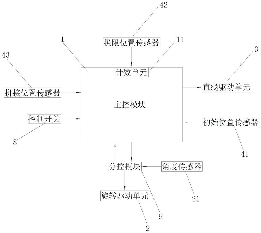
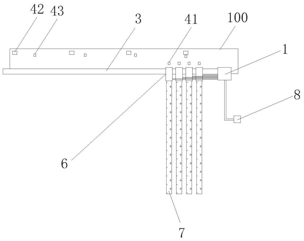
The invention relates to an LED display screen splicing system, device and method. The LED display screen splicing system comprises a main control module, a mounting base, a rotary driving unit, a linear driving unit, a displacement sensor assembly and a sub-control module. The LED display screen is mounted on the mounting base and can be driven by the rotary driving unit so as to realize rotation; the mounting base can be driven by the linear driving unit to move horizontally; the rotation of the LED display screen is controlled by the sub-control module; the movement of the mounting base iscontrolled by the main control module; and the functions of automatic unfolding, splicing, closing and folding of the LED display screen can be achieved. Therefore, a technical means of combining horizontal movement, rotation and displacement sensor assemblies is adopted for LED display screens in the invention; the technical problems that an LED display screen structure occupies a large space andcannot be flexibly applied to a use scene are solved; and the technical effects that the LED display screen can be automatically unfolded and spliced in use, can be folded when not in use and is flexibly applied to various use scenes are achieved.

Description

technical field [0001] The invention relates to the field of LED display screens, in particular to a splicing system, device and method for LED display screens. Background technique [0002] As a screen display device, LED display has been widely used in commercial places such as outdoor advertisements and conference halls. There are also many LED splicing products on the market, but they are mainly for the convenience of transportation. After on-site splicing, in order to ensure the LED display The reliability of the screen is basically fixed structure. For some conference halls, LED displays, as frequently used equipment, basically adopt a fixed structure, but the layout pattern inside the conference hall will often change, and the fixed LED display structure takes up more space and cannot be flexible. Applicable usage scenarios. Contents of the invention [0003] The technical problem to be solved by the embodiments of the present invention is to provide a splicing sy...

Claims


Application Information

Patent Timeline
Patent Type & Authority Applications(China)
IPC IPC(8): G09F9/35G09F9/302G09G3/32
CPCG09F9/3026G09F9/35G09G3/32
Inventor 梁正恺雷再刚龙小云王旭刘君宏
Owner SHENZHEN JIUZHOU OPTOELECTRONICS TECH
Learn More