
Parallel dual-end-surface mechanical seal

A mechanical seal, double-end technology, applied in the field of mechanical seals, can solve the problem of high cost, and achieve the effect of increasing service life, moderate elasticity, and easy inspection and maintenance.

Pending Publication Date: 2020-09-04
鸿浩泵业有限公司
View PDF0 Cites 1 Cited by
  • Summary
  • Abstract
  • Description
  • Claims
  • Application Information

AI Technical Summary

Problems solved by technology

[0002] The mechanical seal is one of the wearing parts of the centrifugal pump. At present, the mechanical seal is divided into single-end mechanical seal and double-end mechanical seal according to the number of sealing surfaces. The single-end mechanical seal is used to transport general corrosive media, and the double-end mechanical seal is used for Conveying toxic and harmful media, the double-end mechanical seals are tandem double-end mechanical seals, including two pairs of dynamic and static rings, and their cost is relatively high. How to apply double-end mechanical seals to centrifugal pumps that convey toxic and harmful media can effectively Cost reduction is an urgent technical problem to be solved

Method used


Image

  • Parallel dual-end-surface mechanical seal
  • Parallel dual-end-surface mechanical seal

Examples


Embodiment Construction

[0026] The present invention will be further described below in conjunction with the accompanying drawings and specific embodiments.

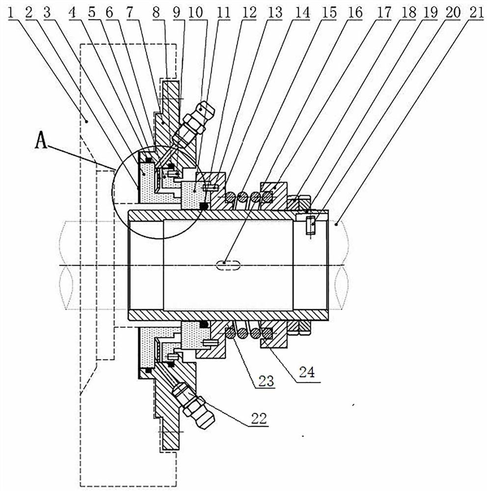
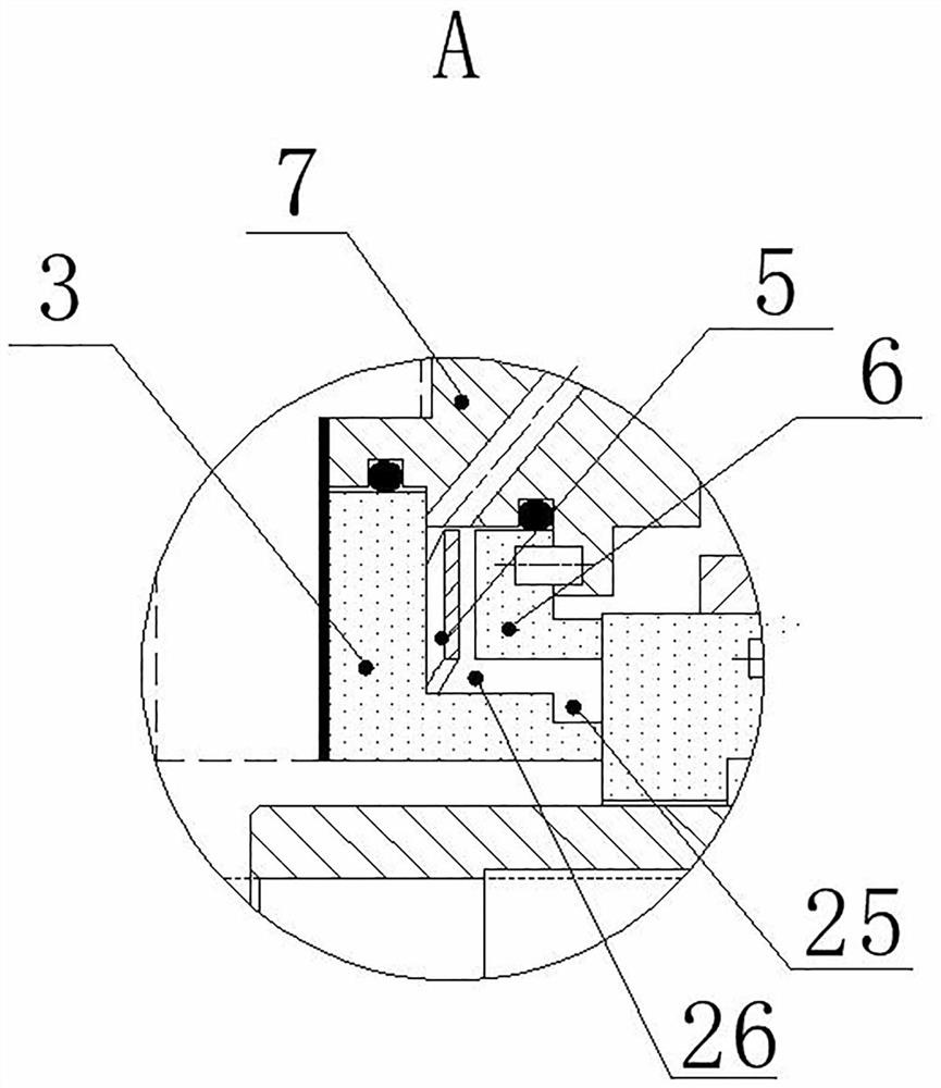
[0027] Such as Figure 1-2 As described above, a parallel double-end mechanical seal includes a moving ring seat 14 that is mounted on the shaft sleeve 19, the shaft sleeve 19 and the moving ring seat 14 rotate integrally, and the shaft sleeve 19 and the moving ring seat 14 pass through the key 16 Connect for transmission. The axle sleeve 19 on one side of the moving ring seat 14 is equipped with a spring seat assembly, and the axle sleeve 19 on the other side of the moving ring seat 14 is equipped with a moving ring 11, and the moving ring 11 is installed with the moving ring seat 14. A second positioning pin 13 is installed between the moving ring seat 14 to ensure the integral rotation of the moving ring 11 and the moving ring seat 14 . The shaft sleeve 19 is installed on the shaft 21 and rotates integrally with the shaft 21, which is real...


PUM


Abstract

The invention belongs to the technical field of mechanical seal and discloses a parallel dual-end-surface mechanical seal. The seal comprises a spring seat exposed and mounted on one side of a shaft sleeve, wherein a pressing component is mounted on one side of the spring seat; a main spring is pressed and mounted on the other side of the spring seat; a movable ring seat capable of integrally rotating with the shaft sleeve is also mounted on the shaft sleeve; the end, away from the spring seat, of the main spring is clamped on one side of the movable ring seat; a movable ring is mounted on theother side of the movable ring seat, and the movable ring is mounted on the shaft sleeve; a first stationary ring and a second stationary ring are mounted on the side end surface of the movable ringin parallel; a cavity is formed between the first stationary ring and the second stationary ring; a wave-shaped spring is mounted in the cavity; a stationary ring pressing cover is mounted on the endsurfaces of the first stationary ring and the second stationary ring; an anti-rotating component is mounted between the second stationary ring and the stationary ring pressing cover; and a flow channel is also obliquely arranged on the stationary ring pressing cover. According to the parallel dual-end-surface mechanical seal, two stationary rings share one movable ring in parallel; the structure is simple and ingenious; the wave-shaped spring is arranged between the two stationary rings; the structure is simple, and the elastic force is moderate; and the parallel dual-end-surface mechanical seal is applied to sealing of cooling water.

Description

technical field [0001] The invention relates to the technical field of mechanical seals, in particular to a parallel double-face mechanical seal. Background technique [0002] The mechanical seal is one of the wearing parts of the centrifugal pump. At present, the mechanical seal is divided into single-end mechanical seal and double-end mechanical seal according to the number of sealing surfaces. The single-end mechanical seal is used to transport general corrosive media, and the double-end mechanical seal is used for Conveying toxic and harmful media, the double-end mechanical seals are tandem double-end mechanical seals, including two pairs of dynamic and static rings, and their cost is relatively high. How to apply double-end mechanical seals to centrifugal pumps that convey toxic and harmful media can effectively Cost reduction is an urgent technical problem to be solved. Contents of the invention [0003] The purpose of the present invention is to solve the technical...

Claims


Application Information

Patent Timeline
IPC IPC(8): F16J15/34F04D29/12F04D29/58
CPCF04D29/12F04D29/58F16J15/3404F16J15/3452F16J15/3464
Inventor 韦尚鹏陈春生
Owner 鸿浩泵业有限公司
Learn More