A selective anticoagulation shock storage device
A storage device and selective technology, applied in transportation and packaging, shaking/oscillating/vibrating mixers, mixers, etc., can solve problems such as inaccurate, misoperation detection results, etc., to ensure detection, reduce misoperation, and facilitate The effect of classification detection
- Summary
- Abstract
- Description
- Claims
- Application Information
AI Technical Summary
Problems solved by technology
Method used
Image

Examples
Embodiment 1
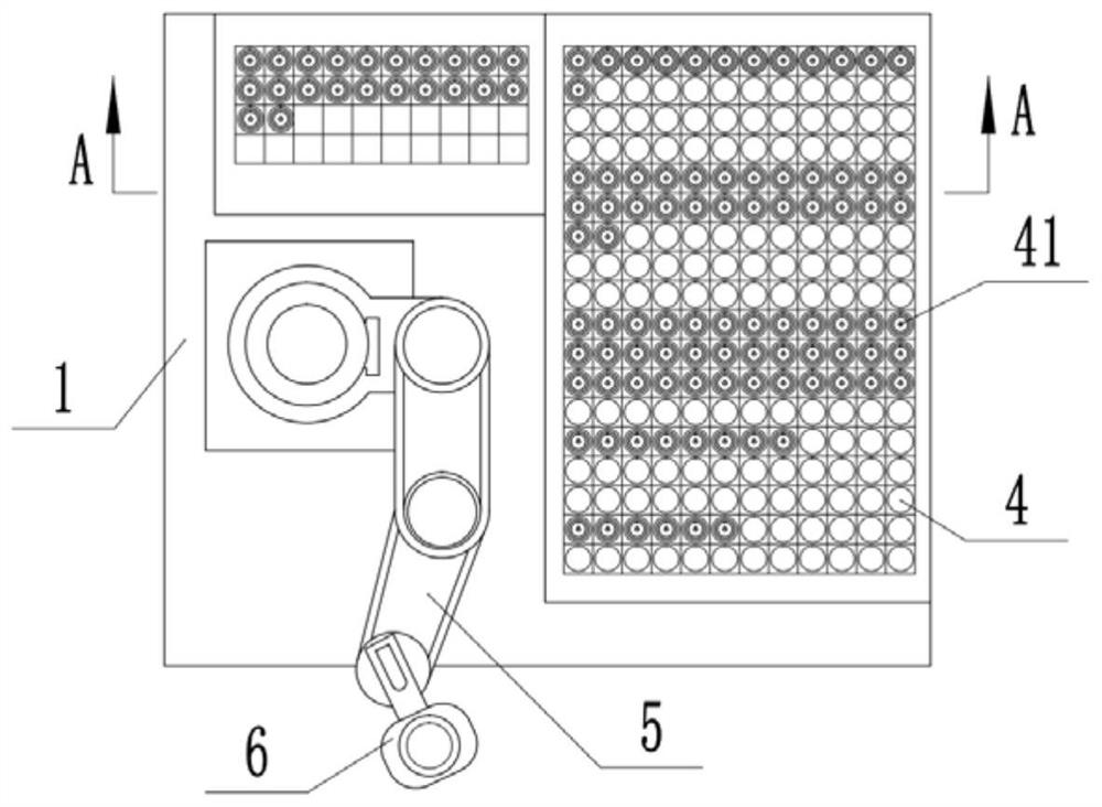
[0039] Embodiment one is basically as attached figure 1 , figure 2 and image 3 Shown: a selective anticoagulation shock storage device, including a storage box 1, the top of the storage box 1 is provided with a placement slot, and the inside of the storage box 1 is fixed with a low-temperature constant temperature bath of model RHD-05 / 20 ( Not shown in the figure), the low-temperature constant temperature tank and the placement tank are communicated through the cold air pipe so that the placement tank forms a low-temperature placement zone 2, and the low-temperature constant temperature effect of the low-temperature constant-temperature tank keeps the temperature of the low-temperature storage zone 2 at a temperature of 2-8 ° C. within range.
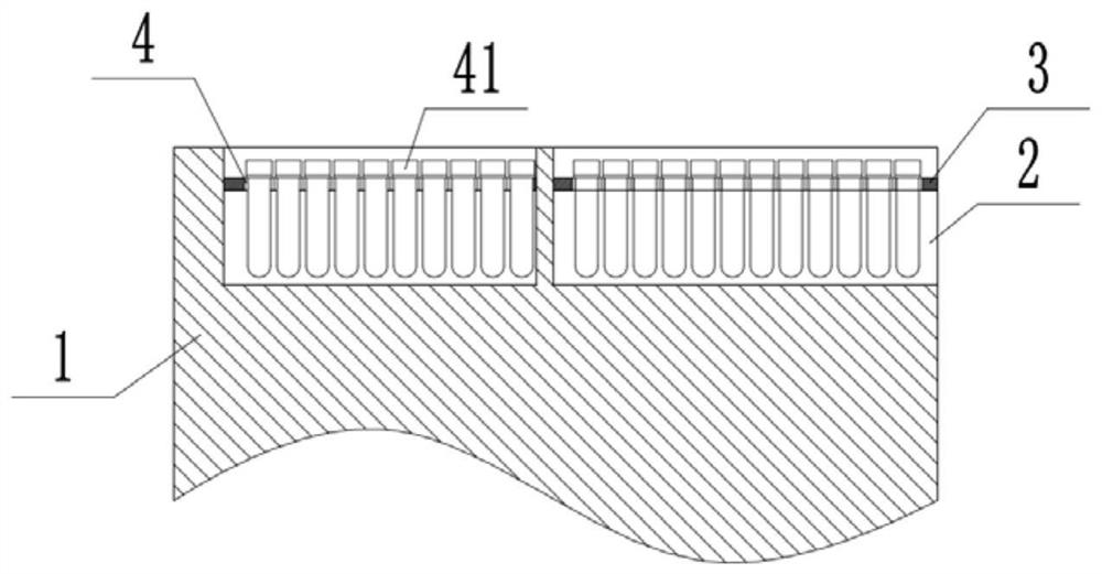
[0040] to combine figure 1 and figure 2 As shown, a support plate 3 is welded in the low temperature storage area 2, and an array-like placement portion 4 is provided on the support plate 3. The diameter of the placement portion ...
Embodiment 2
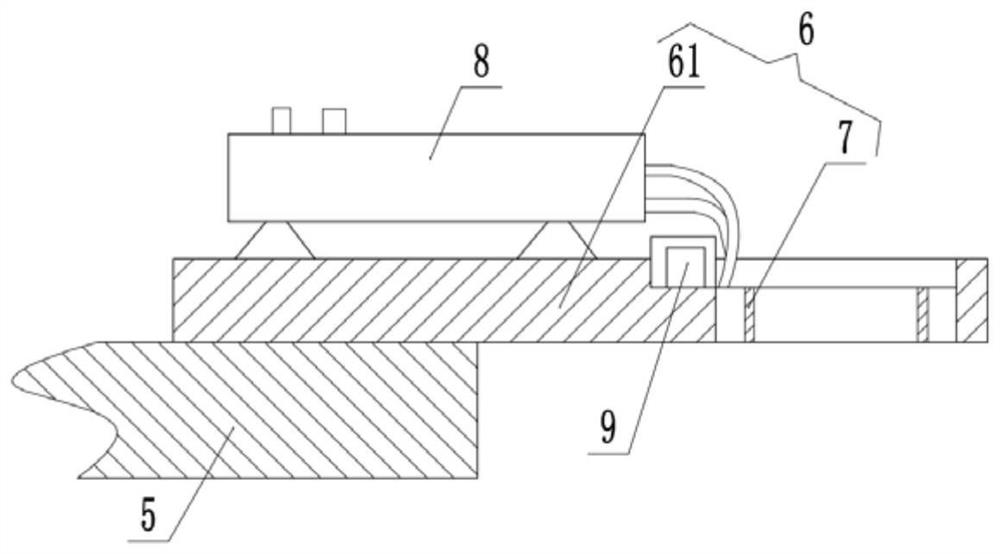
[0050] The difference between embodiment two and embodiment one is: as Figure 4 As shown, the manipulator 5 is fixedly connected with a connection plate 10 by screws, and the connection plate 10 is fixedly connected with a rotary motor 11 with the output shaft facing upwards. The first driving wheel 12 is fixedly connected by screws, and the connecting plate 10 is connected with the first driven wheel 13 meshing with the first driving wheel 12 through bearing rotation at the same time, and the clamping block 61 is fixedly connected on the first driven wheel 13 by screws , and the clamping hole on the clamping block 61 is set coaxially with the first driven wheel 13 .
[0051] When the test tube 41 needs to be mixed upside down, the single-chip microcomputer controls the manipulator 5 to rotate the connecting plate 10, and when the connecting plate 10 rotates, the clamping block 61 and the test tube 41 clamped on the clamping block 61 are driven to mix upside down; Control th...
Embodiment 3
[0053] The difference between embodiment three and embodiment two is: as Figure 5 , Figure 6 and Figure 7 as shown, figure 2 The top of the medium and low temperature storage area 2 is rotated and connected with a cover plate 14 that covers the low temperature storage area 2 through a pin shaft mode. The cover plate 14 is provided with a cover assembly that covers or opens a row of placement parts 4, and the cover plate 14 is opened. There are placement grooves corresponding to the number of rows of placement parts 4 . In this embodiment, the cover assembly includes a rotating plate 15 that is rotatably connected in the placement groove through a pin shaft connection. The cover plate 14 is provided with a second driving member that selectively drives the rotating plate 15 to rotate. The second driving member includes a first Two driving motors 16 and the second driving wheel 17 that are fixedly connected to the second driving motor 16 output shafts by screws, the second...
PUM
 Abstract
Description
Claims
Application Information
 - R&D
- Intellectual Property
- Life Sciences
- Materials
- Tech Scout
- Unparalleled Data Quality
- Higher Quality Content
- 60% Fewer Hallucinations
Browse by: Latest US Patents, China's latest patents, Technical Efficacy Thesaurus, Application Domain, Technology Topic, Popular Technical Reports.
© 2025 PatSnap. All rights reserved.Legal|Privacy policy|Modern Slavery Act Transparency Statement|Sitemap|About US| Contact US: help@patsnap.com