
Multipurpose mobile equipment support

A mobile device, multi-purpose technology, applied in the field of support frame, can solve the problems of complicated operation, inconvenient use, unfavorable carrying, etc., and achieve the effect of enhancing the use length, optimizing the use volume, and occupying a small area.

Inactive Publication Date: 2020-08-28
程志刚
View PDF6 Cites 1 Cited by
  • Summary
  • Abstract
  • Description
  • Claims
  • Application Information

AI Technical Summary

Problems solved by technology

[0002] Nowadays, people often need mobile phone brackets to support when looking at mobile phones in their daily lives. However, because the mobile phone brackets on the market can bend and turn through the cantilever itself (for example, the cantilever is thick iron wire), it is limited by the characteristics of the material itself. If the cantilever is thin, it cannot be used. To achieve strong support, but thick cantilever will require a lot of force when bending and turning, in order to achieve the bending effect and cannot accurately reach the ideal hovering position; through the bending and steering of parts composed of multi-section cantilever and steering joint, It is necessary to set fastening devices at the joints to achieve steering angle control and requires the cooperation of multiple steering joints
Whether it is through the bending of the cantilever itself or the bending and steering of components composed of multi-section cantilever and steering joints, there are disadvantages of inconvenient use and cumbersome operation in the actual scene where the hovering position needs to be constantly adjusted.
[0003] The above-mentioned device brackets are restricted by the design itself, and cannot be used in other scenarios in terms of function, and cannot be reduced for storage, which is not conducive to carrying. In addition, most power-consuming devices (such as mobile phones) need to charge the equipment during the use of the bracket. , the existing equipment support cannot meet the requirements of the integrated design

Method used


Image

  • Multipurpose mobile equipment support
  • Multipurpose mobile equipment support
  • Multipurpose mobile equipment support

Examples


Embodiment Construction

[0030] The following will clearly and completely describe the technical solutions in the embodiments of the present invention with reference to the accompanying drawings in the embodiments of the present invention. Obviously, the described embodiments are only some, not all, embodiments of the present invention. Based on the embodiments of the present invention, all other embodiments obtained by persons of ordinary skill in the art without making creative efforts belong to the protection scope of the present invention.

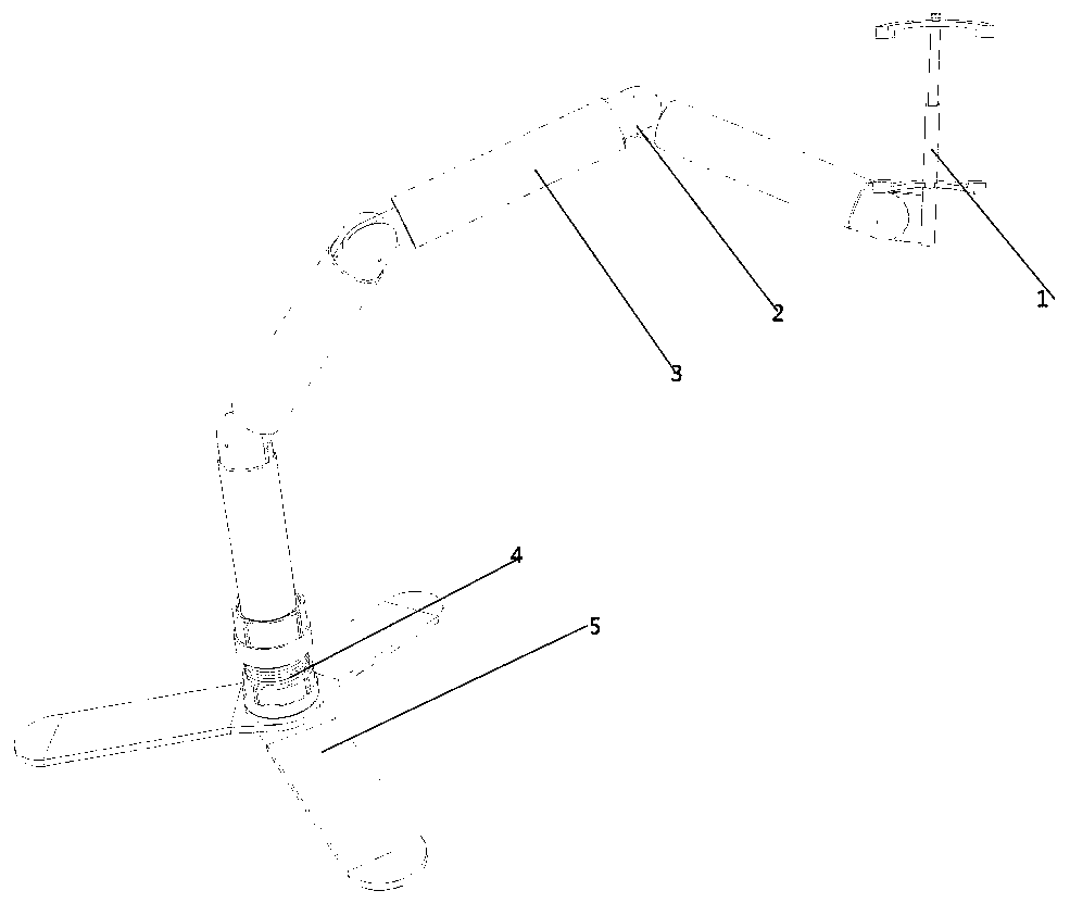
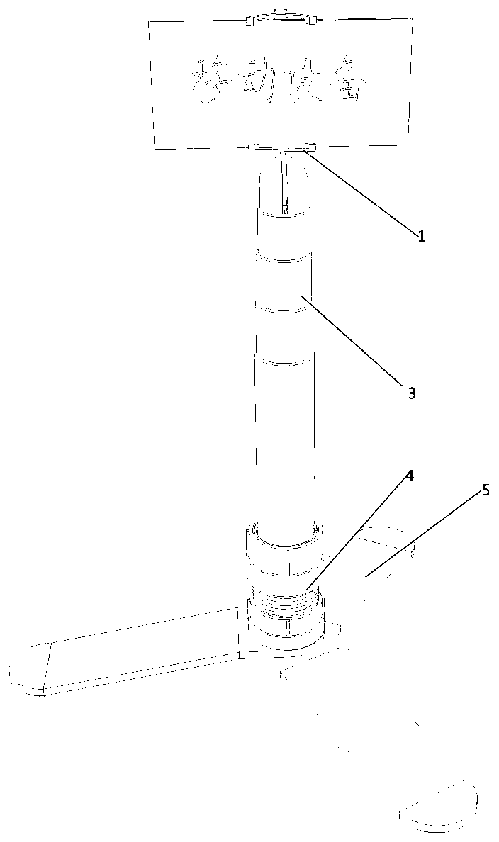
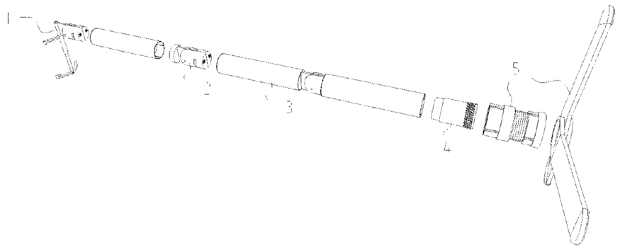
[0031] Please refer to the attached Figure 1-13 , which is a multi-purpose mobile equipment bracket disclosed by the present invention.

[0032] The present invention mainly includes: a support clamp assembly 5, a power supply assembly 4, a telescopic sleeve 3, a steering joint assembly 2, and an equipment fixture assembly 1; wherein, the telescopic sleeve 3 is a multi-stage bending arm, and The telescopic sleeves 3 are connected through the steering knuckle...


PUM


Abstract

The invention discloses a multipurpose mobile equipment support. A telescopic sleeve pipe is a multi-section bendable arm, every two adjacent telescopic sleeve pipe sections are connected through a steering joint assembly, a power supply assembly is arranged in the telescopic sleeve pipe and fixed to a supporting and clamping assembly, and support is achieved by changing the positions of supporting and clamping rods. Steering is adjusted through the steering joint assemblies, sleeve pipe sections of different diameters can stretch out and draw back through the telescopic sleeve pipe, and the power supply assembly supplies power to an equipment clamp assembly through cooperation of the telescopic sleeve pipe and the steering joint assemblies. The size is optimized through the telescopic sleeve pipe, the use length is increased, a multi-section mechanism is formed through the connection of the steering joint assemblies, and use in multiple directions can be achieved. Moreover, the powersupply assembly is additionally arranged in the sleeve pipe, current conduction is achieved through connection of the sleeve pipe sections and the steering joint assemblies, and charging is carried out through a charging wire. The multipurpose mobile equipment support has the advantages of being simple to operate, convenient to use, small in occupied area and high in functionality.

Description

technical field [0001] The invention relates to the technical field of support frames, and more specifically relates to a multipurpose mobile equipment support. Background technique [0002] Nowadays, people often need mobile phone brackets to support when looking at mobile phones in their daily lives. However, because the mobile phone brackets on the market can bend and turn through the cantilever itself (for example, the cantilever is thick iron wire), it is limited by the characteristics of the material itself. If the cantilever is thin, it cannot be used. To achieve strong support, but thick cantilever will require a lot of force when bending and turning, in order to achieve the bending effect and cannot accurately reach the ideal hovering position; through the bending and steering of parts composed of multi-section cantilever and steering joint, Fastening devices need to be provided at joints to realize steering angle control and cooperation of multiple steering knuckle...

Claims


Application Information

Patent Timeline
Patent Type & Authority Applications(China)
IPC IPC(8): F16M11/04F16M11/28
CPCF16M11/04F16M11/2035F16M11/28
Inventor 程志刚
Owner 程志刚
Learn More