A protection mechanism for preventing a second firing of a stapler, a stapler and a staple cartridge
A protection mechanism and secondary firing technology, applied in the field of medical devices, can solve the problems of increasing installation difficulty, inability to guarantee an empty nail cartridge protection mechanism, complex structure, etc., to prevent secondary firing, low production cost, and easy modification Effect
- Summary
- Abstract
- Description
- Claims
- Application Information
AI Technical Summary
Problems solved by technology
Method used
Image
Examples
Embodiment 1
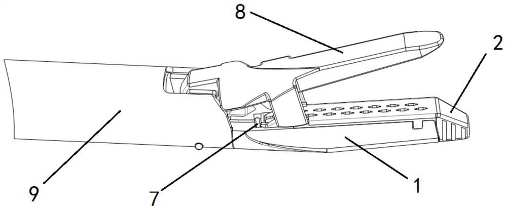
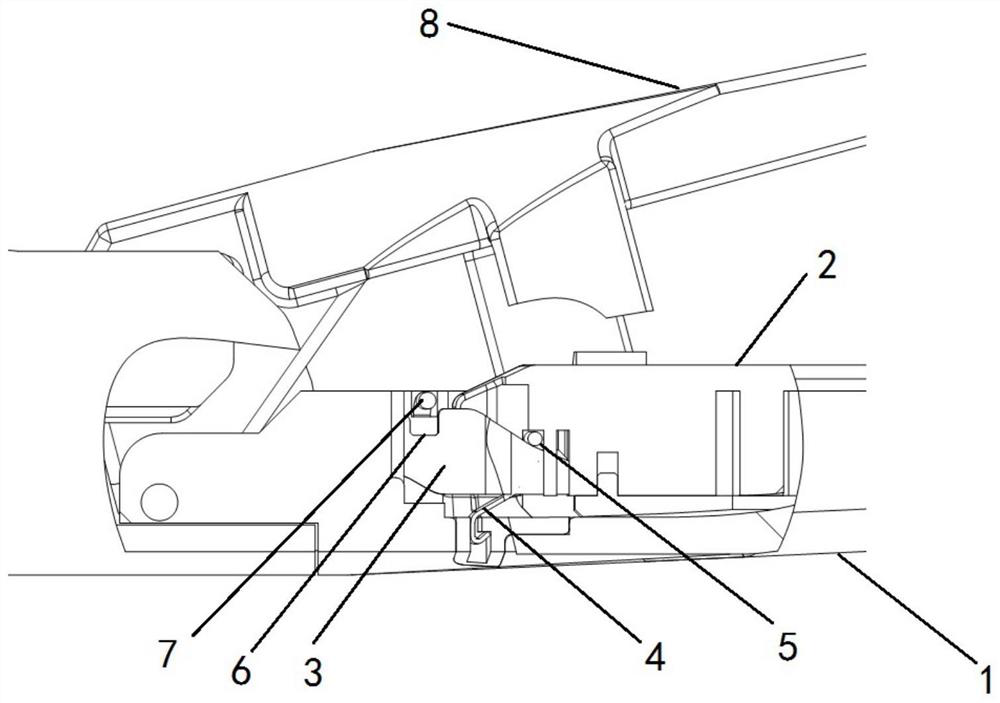
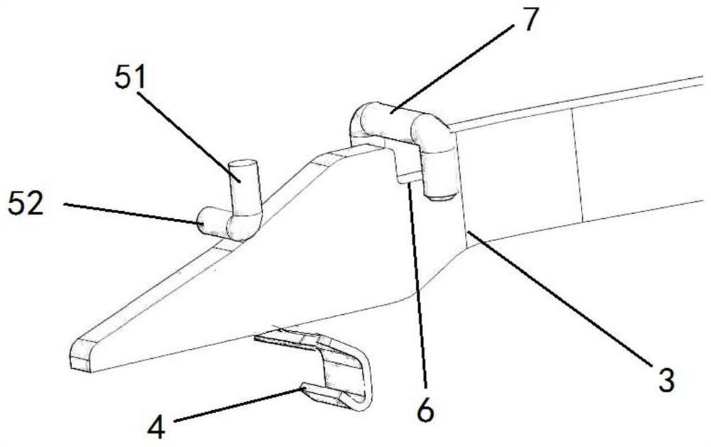
[0031] Such as Figure 1-6 As shown, the present embodiment provides a protection mechanism for preventing the second firing of the stapler. Specifically, the stapler includes an execution end, and the execution end includes a staple cartridge accommodating portion 1, a staple cartridge 2, a pusher driver 3, and an anvil. The seat 8 and the connecting pipe 9, wherein the staple cartridge housing part 1 is fixedly connected to the connecting pipe 9, the anvil 8 is hinged to the connecting pipe 9, the staple cartridge 2 is installed in the nail cartridge containing part 1, and the nail pushing driver 3 passes through the connecting pipe The tube 9 is connected with the driving mechanism, and the upper surface of the pusher driver 3 includes a horizontal plane and an inclined plane; the pusher driver 3 can move between the initial position and the firing position under the driving of the drive mechanism; When the position is moving to the firing position, the inclined surface of ...
Embodiment 2
[0039]In this embodiment, the difference from Embodiment 1 is that the pressing member 5 is fixed on the staple cartridge 2, and when the pushing driver 3 moves from the initial position to the firing position, the pressing member 5 can be destroyed so that it is located at the disengagement position, wherein The pressing part 5 is made of easily destructible materials, such as brittle plastics, or thin elastic parts, so that when the push nail driver 3 is pushed forward, the structure of the pressing part 5 is directly destroyed, so that its position is invalid. At this time, the state of the broken pressing member 5 is the disengagement position. In this embodiment, the pressing member 5 adopts such an arrangement structure, which can be more convenient, and the installation process is also simpler. Or in other ways, as long as the pressing member is set to be able to be pushed away from the current position, the design that no longer presses down on the push nail driver aft...
Embodiment 3
[0041] In this embodiment, a staple cartridge is protected, and the staple cartridge has a lower pressing member 5, which is an L-shaped stop pin, and the L-shaped stop pin is pivotally connected with the staple cartridge 2, and the L-shaped stop pin includes a vertical The straight part 51 and the horizontal part 52 perpendicular to the vertical part 51, the vertical part 51 and the staple cartridge 2 are pivotally connected, and the axis of the pivot connection is perpendicular to the nail pushing direction of the push nail driver 3, and the nail cartridge 2 also includes a The accommodating cavity 21 that accommodates the horizontal portion 52 of the L-shaped limiting pin, when the L-shaped limiting pin is in the depressed position, the horizontal portion 52 of the L-shaped limiting pin is located in the accommodating cavity 21, and the staple cartridge is used to cooperate with the In the stapler of Embodiment 1, it forms the effect of protecting the empty staple cartridge ...
PUM
 Abstract
Description
Claims
Application Information
 - R&D
- Intellectual Property
- Life Sciences
- Materials
- Tech Scout
- Unparalleled Data Quality
- Higher Quality Content
- 60% Fewer Hallucinations
Browse by: Latest US Patents, China's latest patents, Technical Efficacy Thesaurus, Application Domain, Technology Topic, Popular Technical Reports.
© 2025 PatSnap. All rights reserved.Legal|Privacy policy|Modern Slavery Act Transparency Statement|Sitemap|About US| Contact US: help@patsnap.com


