
Improved storage shelf

An improved technology for storage shelves, which is applied in the direction of adjustable cabinets, household appliances, storage devices, etc., can solve the problems of sliding shelf compartments, low utilization of storage shelves, and low space utilization, so as to avoid rigid damage, The effect of improving the range of use and utilization

Active Publication Date: 2020-08-25
浙江奕星达智慧科技有限公司
View PDF6 Cites 0 Cited by
  • Summary
  • Abstract
  • Description
  • Claims
  • Application Information

AI Technical Summary

Problems solved by technology

[0003] 1. The distance between the compartments of common storage shelves and the width of the compartments cannot be adjusted. When storing and arranging goods, it is easy to cause insufficient palletizing and storage of goods due to the small space between the compartments or excessive surplus. , that is, the space utilization is low, and at the same time, the overall stability of the goods stored on the storage shelves is low and it is easy to loose due to external forces, and the goods are easy to accumulate dust and other impurities and be affected by moisture because they are exposed;
[0004] 2. The relative sliding phenomenon is easy to occur between the tubular goods stored on the storage shelf and between the goods and the shelf compartment, and the tubular goods are more likely to slip off the shelf compartment under the action of external forces. At the same time, the storage shelf is on the surface. It is impossible to make adaptive adjustments for the goods that need to be hung and stored, and the overall utilization of storage shelves is low

Method used


Image

  • Improved storage shelf
  • Improved storage shelf
  • Improved storage shelf

Examples


Embodiment Construction

[0037] The embodiments of the present invention will be described in detail below with reference to the accompanying drawings, but the present invention can be implemented in many different ways as defined and covered by the claims.

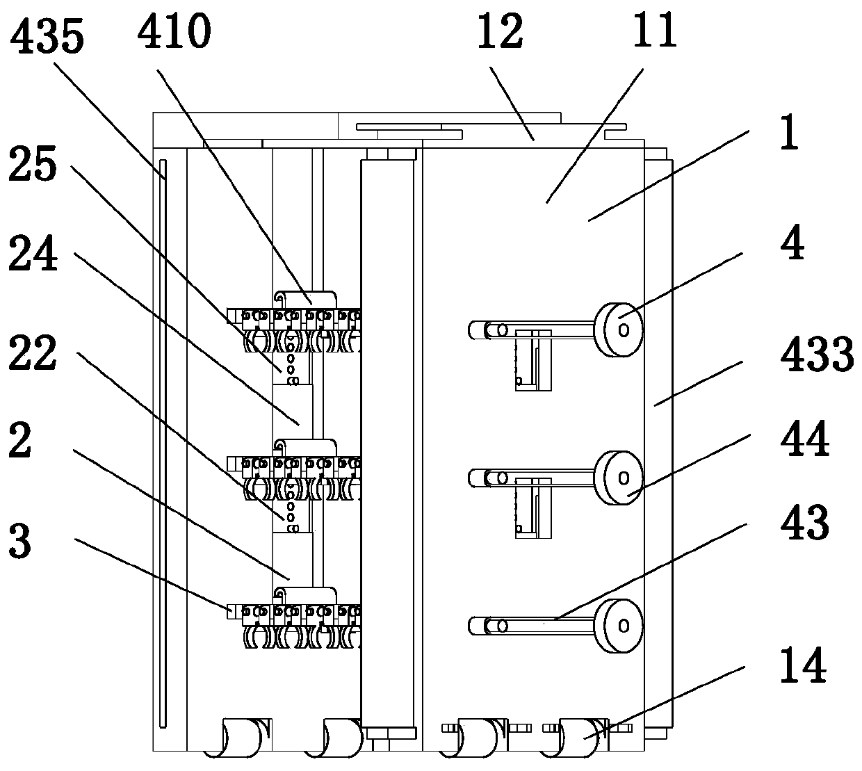
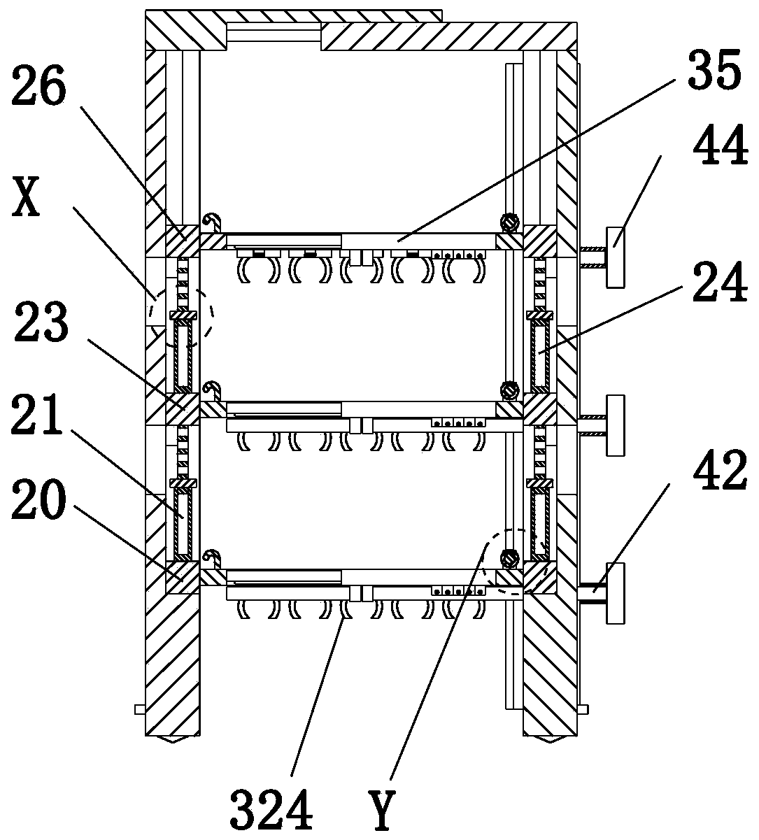
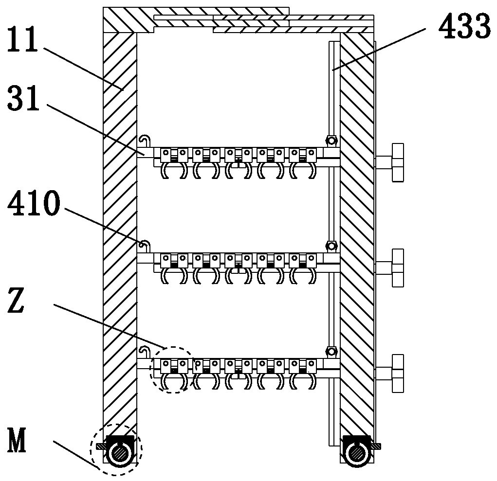
[0038] like Figure 1 to Figure 12 As shown, an improved storage shelf includes a frame body mechanism 1, a height adjustment mechanism 2, a plate group 3 and a width adjustment mechanism 4. The lower end of the frame body mechanism 1 is installed on the existing working ground by sliding fit. The frame mechanism 1 is arranged left and right, the inner end of the frame mechanism 1 is installed with a height adjustment mechanism 2 through a sliding fit, and the plate group 3 is installed equidistantly from top to bottom between the height adjustment mechanisms 2, and the lower right end of the plate group 3 Width adjustment mechanism 4 is installed.

[0039] The frame body mechanism 1 includes a vertical frame 11, a top plate 12, a connecting sha...


PUM


Abstract

The invention relates to an improved storage shelf. The improved storage shelf comprises a shelf body mechanism, height adjusting mechanisms, plate sets and a width adjusting mechanism. The lower endof the shelf body mechanism is installed on the existing working ground in a sliding-fit mode. The shelf body mechanism is arranged bilaterally. The inner side end of the shelf body mechanism is provided with the height adjusting mechanisms in a sliding-fit mode. The plate sets are installed between the height adjusting mechanisms from top to bottom at equal intervals. The width adjusting mechanism is installed at the lower ends of the plate sets. By adopting the design idea of the longitudinal and transverse size adjustable structure for cargo storage, reasonable distribution and partitioningcan be performed in the space among the plate sets and the space among the existing working ground, the plate sets and the top plate according to the stored cargo type by arranging the height adjusting mechanisms, and suitability adjustment can be performed on the longitudinal length of the plate sets by arranging the width adjusting mechanism, so that the purposes of enlarging the application range of the whole storage shelf and increasing the utilization rate of the whole storage shelf are achieved.

Description

technical field [0001] The invention relates to the technical field of shelf manufacturing, in particular to an improved storage shelf. Background technique [0002] Warehouse shelf refers to the stretcher used to place goods in the warehouse. It is widely used in industrial warehouses. It focuses more on upward development and makes full use of storage space. The maximum height can reach more than 40 meters. It is mainly made of steel after rolling, positioning and It is made of punching, bending, welding and surface treatment. There are also a few warehouse shelves made of plastic and other materials. Shelves occupy a very important position in logistics and warehouses. With the rapid development of modern industry, logistics In order to realize the modern management of the warehouse and improve the function of the warehouse, not only a large number of shelves are required, but also multi-functional, and can realize mechanization and automation requirements. Storage shelve...

Claims


Application Information

Patent Timeline
IPC IPC(8): B65G1/04A47B57/20
CPCA47B57/20B65G1/04
Inventor 王鑫杰金双
Owner 浙江奕星达智慧科技有限公司
Learn More