
Die with ejector sleeve ejection structure

A cylinder and mold technology, applied in the field of injection molds, can solve problems such as tolerance, inability to guarantee the glue position of the boss, influence, etc., and achieve the effects of meeting product tolerance requirements, protecting the appearance surface, and facilitating demoulding

Inactive Publication Date: 2020-08-25
中山市利群精密实业有限公司
View PDF8 Cites 1 Cited by
  • Summary
  • Abstract
  • Description
  • Claims
  • Application Information

AI Technical Summary

Problems solved by technology

However, when the boss is surrounded by the appearance surface, the ejection of the front mold thimble or inserts will have a bad effect on the appearance surface. At this time, the mold can only be released by increasing the draft angle, but the boss glue cannot be guaranteed. bit tolerance

Method used


Image

  • Die with ejector sleeve ejection structure
  • Die with ejector sleeve ejection structure
  • Die with ejector sleeve ejection structure

Examples


Embodiment Construction

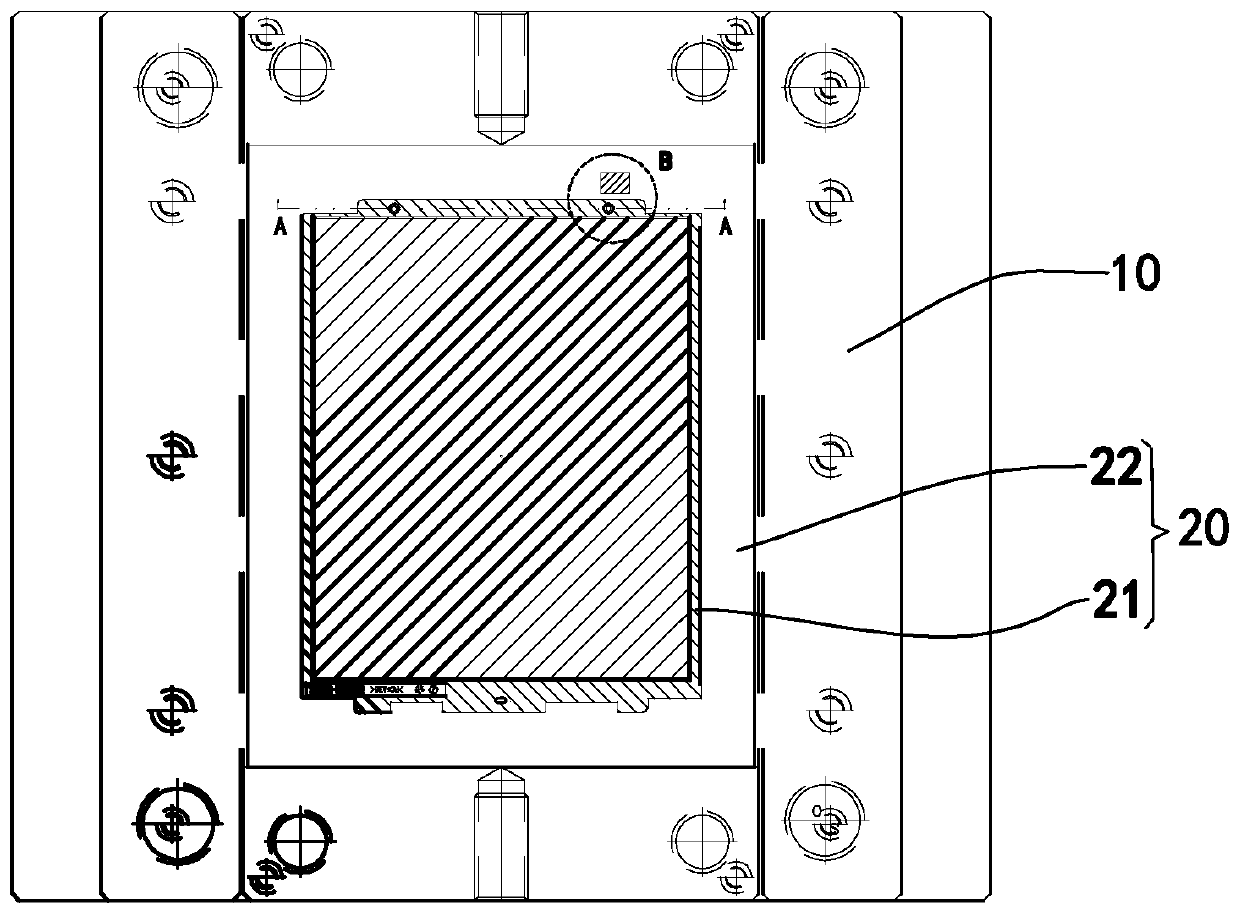
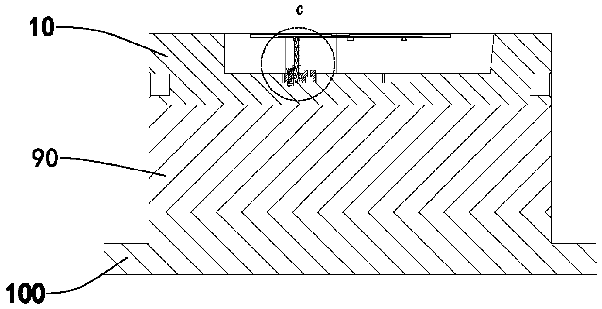
[0019] Such as Figure 1 to Figure 4 As shown, the present embodiment provides a mold with a cylinder ejection structure, including a template 10, a module 20, a fixing plate 30, an insert pin 40, a cylinder 50, an elastic block 60, an elastic member 70, a pressing block 80, Stripper plate 90 and front mold panel 100.

[0020] Wherein, the module 20 is connected with the template 10 , and the module 20 can be embedded in the installation groove on the front of the template 10 . In this embodiment, the template 20 is connected on the stripper plate 90, and the stripper plate 90 is connected on the front mold panel 100, and the front mold panel 100, the stripper plate 90, the module 20 and the template 10 etc. constitute a front mold, The molds are matched to form a complete mold for injection molding, and the front mold is also provided with a flow channel for the plastic material to pass through.

[0021] The surface of the module 20 comprises a profiled area 21 and a contac...


PUM


Abstract

The invention relates to a die with an ejector sleeve ejection structure. A template, a die block, a fixing plate, an inlaying needle, an ejector sleeve, an elastic block and an elastic piece are included. The fixing plate is fixed to the template or fixed to the bottom of the die block. The first end of the inlaying needle is connected with the fixing plate, the ejector sleeve is movably in cup joint to the inlaying needle, and a protruding block is arranged at the first end of the ejector sleeve. The ejector sleeve movably penetrates through the die block, and the second end of the inlayingneedle and the second end of the ejector sleeve lead to the forming area. A groove is formed in the first end of the elastic block and matched with the protruding block and comprises a stop wall located on side, close to the second end of the ejector sleeve, of the protruding block. The elastic block movably penetrates through the die block, and the second end of the elastic block leads to the contact area. The first end of the elastic piece is connected with the template or the fixing plate, and the second end of the elastic piece is connected with the first end of the elastic block. The sideface, away from the second end of the ejector sleeve, of the protruding block is connected with the second end of the elastic piece or connected with the groove. During die stripping, the appearanceface and boss glue position tolerance are not influenced.

Description

technical field [0001] The invention relates to the technical field of molds for injection molding, in particular to a mold with a cylinder ejection structure. Background technique [0002] Mold injection molding is a common molding method for preparing plastic products. Sometimes the product has a boss structure, such as a small ring-shaped raised boss. After injection molding, the raised part is usually embedded in the mold. Existing molds usually adopt structures such as front mold thimbles or inserts with springs to push out the convex part of the product embedded in the mold when the mold is opened. However, when the boss is surrounded by the appearance surface, the ejection of the front mold thimble or inserts will have a bad effect on the appearance surface. At this time, the mold can only be released by increasing the draft angle, but the boss glue cannot be guaranteed. bit tolerance. Contents of the invention [0003] In view of the deficiencies of the prior art...

Claims


Application Information

Patent Timeline
Patent Type & Authority Applications(China)
IPC IPC(8): B29C45/26B29C45/44
CPCB29C45/2602B29C45/4435B29C2045/4442B29C2045/4492
Inventor 张旭张建群张宇昂戴飞军何可梅
Owner 中山市利群精密实业有限公司
Learn More