
Motor driving method and driving device

A technology of motor drive and drive pulse, which is applied in the direction of AC motor control, output power conversion device, electrical components, etc., and can solve problems affecting the stability of equipment, etc.

Active Publication Date: 2020-08-21
DUNSHI MAGNETIC ENERGY TECH +1
View PDF5 Cites 4 Cited by
  • Summary
  • Abstract
  • Description
  • Claims
  • Application Information

AI Technical Summary

Problems solved by technology

[0004] In view of this, the embodiment of the present invention provides a motor driving method and a driving device to solve the problem in the prior art that the switching element is switched multiple times in one sector, which affects the stability of the device

Method used


Image

  • Motor driving method and driving device
  • Motor driving method and driving device
  • Motor driving method and driving device

Examples


Embodiment Construction

[0027] In the following description, specific details such as specific system structures and technologies are presented for the purpose of illustration rather than limitation, so as to thoroughly understand the embodiments of the present invention. It will be apparent, however, to one skilled in the art that the invention may be practiced in other embodiments without these specific details. In other instances, detailed descriptions of well-known systems, devices, circuits, and methods are omitted so as not to obscure the description of the present invention with unnecessary detail.

[0028] In order to illustrate the technical solutions of the present invention, specific examples are used below to illustrate.

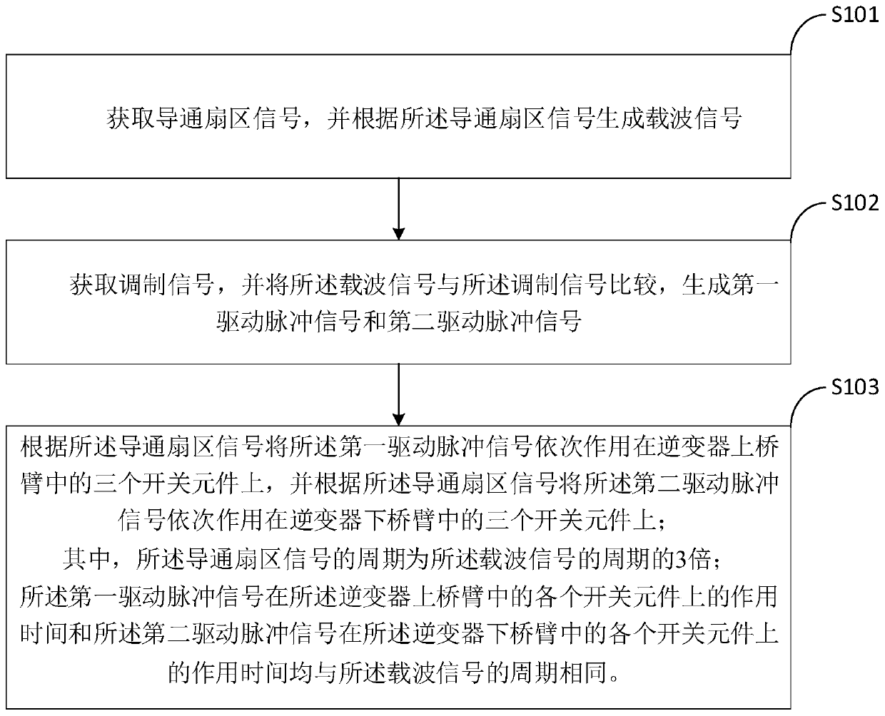
[0029] refer to figure 2 , an embodiment of the present invention provides a motor driving method, including:

[0030] Step S101: Obtaining the signal of the turned-on sector, and generating a carrier signal according to the signal of the turned-on sector;

[0031] ...


PUM


Abstract

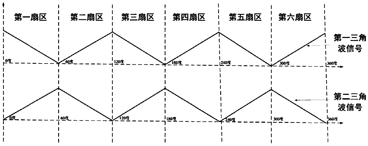
The invention is suitable for the technical field of permanent magnet synchronous motors, and provides a motor driving method and device, and the method comprises the steps: generating a first drivingpulse signal and a second driving pulse signal according to a conduction sector signal; sequentially acting a first driving pulse signal on the three switching elements in the upper bridge arm of theinverter according to the conduction sector signal, and sequentially acting a second driving pulse signal on the three switching elements in the lower bridge arm of the inverter according to the conduction sector signal. The period of the conduction sector signal is three times of the period of the carrier signal; and the action time of the first driving pulse signal on each switching element inthe upper bridge arm of the inverter and the action time of the second driving pulse signal on each switching element in the lower bridge arm of the inverter are the same as the period of the carriersignal. According to the driving method provided by the invention, each switching element of the inverter is switched on and off only once in each electrical period, so that the switching loss is reduced, the heat productivity and the heat dissipation difficulty of equipment are reduced, and the stability of the equipment is improved.

Description

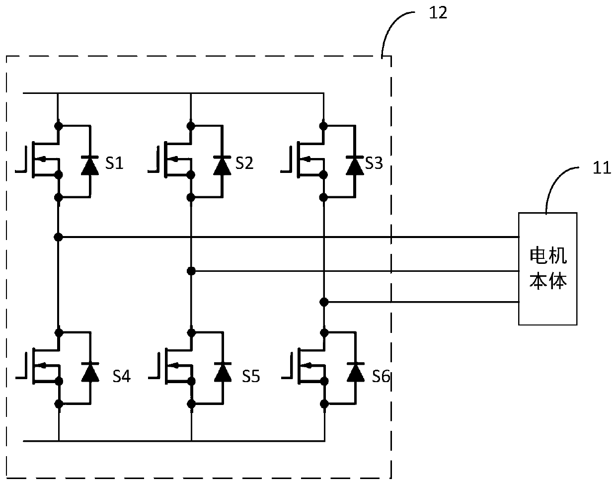
technical field [0001] The invention belongs to the technical field of permanent magnet synchronous motors, and in particular relates to a motor driving method and a driving device. Background technique [0002] With the development of power electronics technology, high-speed permanent magnet motors are more and more used in industry and production and life due to their high power density, low noise and high environmental friendliness. [0003] In prior art, refer to figure 1 , The control system of the high-speed permanent magnet motor is composed of a digital PWM (Pulse width modulation, pulse width modulation) controller and power switching elements (S1, S2, S3, S4, S5 and S6). When the driving power of the high-speed motor (motor body 11) reaches a certain level, the switching loss of the power device will be significantly increased due to the multiple switching of the switching element in one sector by the existing control method, and the equipment efficiency will be r...

Claims


Application Information

Patent Timeline
Patent Type & Authority Applications(China)
IPC IPC(8): H02P27/08H02M7/5387H02M7/5395
CPCH02M7/5387H02M7/5395H02P27/08H02M1/0054Y02B70/10
Inventor 赵思锋陈鹰唐英伟梁艳召张建平
Owner DUNSHI MAGNETIC ENERGY TECH
Learn More