
Brush disc structure and cleaning robot

A technology for cleaning robots and brushing disks, applied in cleaning machinery, robot cleaning machines, cleaning equipment, etc., can solve the problem of small operation space, difficult operation, and difficulty in directly observing the card connection between the brushing disk and the bottom of the cleaning robot. Position and other issues to achieve the effect of improving the docking accuracy and simplifying the installation and disassembly process

Active Publication Date: 2020-08-18
苏州高之仙自动化科技有限公司 +1
View PDF10 Cites 2 Cited by
  • Summary
  • Abstract
  • Description
  • Claims
  • Application Information

AI Technical Summary

Problems solved by technology

[0005] The purpose of the present invention is to provide a brush plate structure and a cleaning robot to alleviate the problem in the prior art that when the brush plate is installed and removed on the bottom of the cleaning robot, the position where the bottom of the cleaning robot is clamped with the brush plate is raised Finally, the operating space between it and the ground is still small, and it is difficult for the operator to directly observe the clamping position between the brush plate and the bottom of the cleaning robot, which makes the operation of the brush plate installation and removal process difficult and inconvenient. higher technical issues

Method used


Image

  • Brush disc structure and cleaning robot
  • Brush disc structure and cleaning robot
  • Brush disc structure and cleaning robot

Examples


Embodiment 1

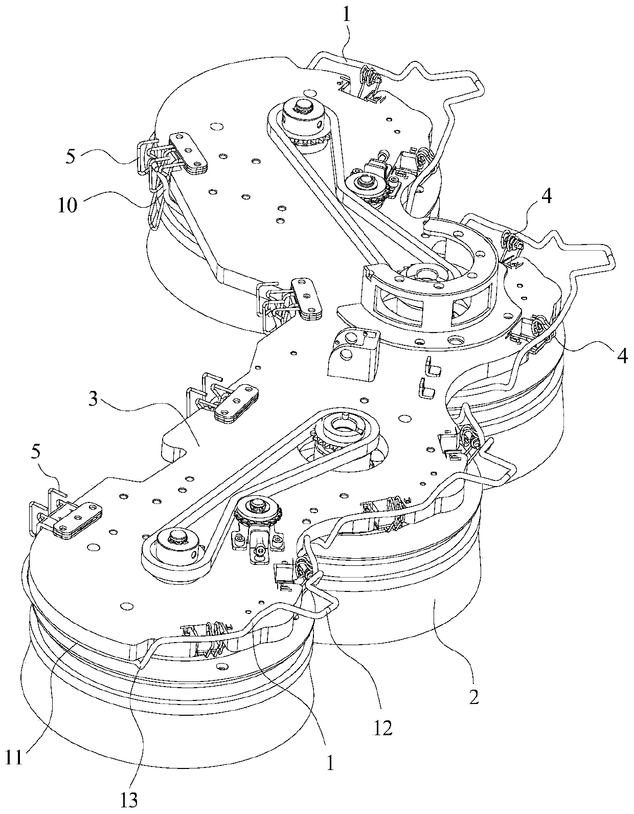
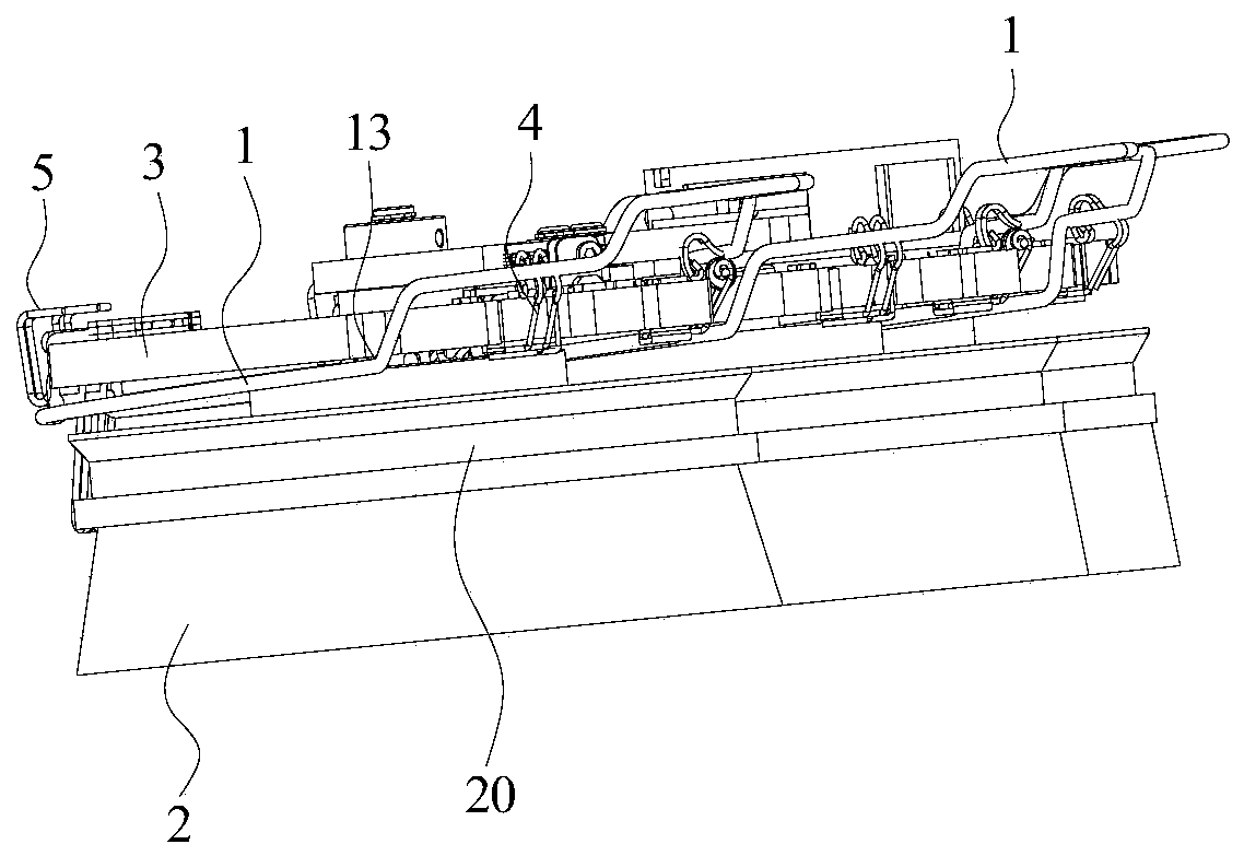
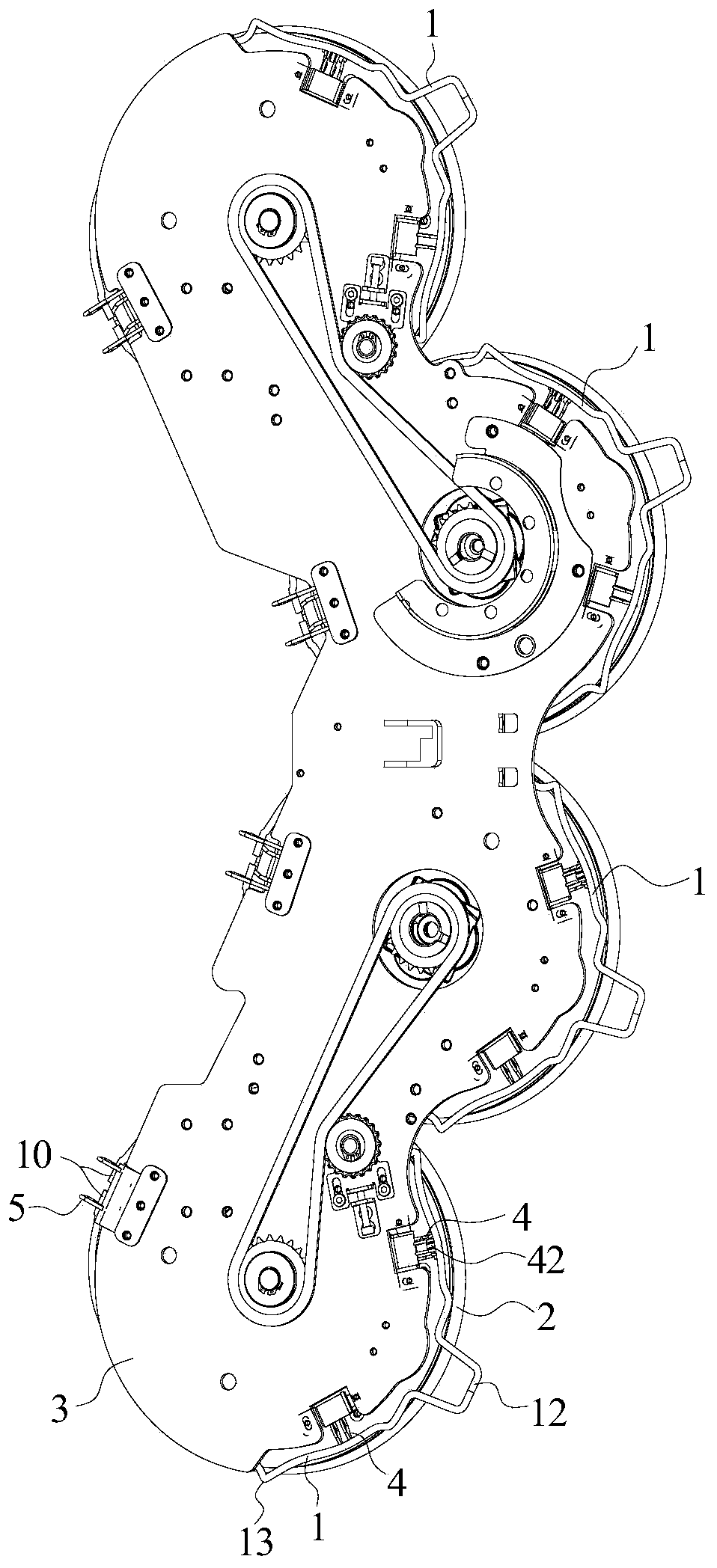
[0049] Such as figure 1 , figure 2 , image 3 and Figure 4 As shown, the brush tray structure provided in this embodiment includes an installation and removal frame 1 and a brush tray 2, and the brush tray 2 can be clipped to the bottom of the cleaning robot. The installation and removal frame 1 is provided with a hinged part 10, and the hinged part 10 is hinged on the bottom of the cleaning robot. The installation and removal frame 1 can be connected with the brush plate 2, and the installation and removal frame 1 can be rotated with the hinge 10 as the rotation center to drive the brush plate 2 to be clamped on the bottom of the cleaning robot, or to drive the brush plate 2 from the bottom of the cleaning robot up and out.

[0050] When the brush tray 2 needs to be disassembled, first utilize the lifting mechanism on the cleaning robot to raise the brush tray 2, and leave an operation space for removing the brush tray 2 between the brush tray 2 and the ground. Then th...

Embodiment 2

[0092] Such as Figure 7 As shown, the cleaning robot provided in this embodiment includes the brush plate structure in the first embodiment.

[0093] Further, such as Figure 7 As shown, the bottom of the cleaning robot is provided with a brush plate mounting plate 3 , and the brush plate 2 is clamped on the brush plate mounting plate 3 .

[0094] The cleaning robot provided in this embodiment includes the brush plate structure in the first embodiment, so the cleaning robot provided in this embodiment and the brush plate structure in the first embodiment can solve the same technical problems and achieve the same technical effect. The cleaning robot provided by this embodiment also alleviates the problem in the prior art that when the brush plate is installed and removed on the bottom of the cleaning robot, after the position where the bottom of the cleaning robot is engaged with the brush plate is raised, the distance between it and the ground The remaining operating space ...


PUM


Abstract

The invention provides a brush disc structure and a cleaning robot, and relates to the technical field of cleaning devices. The brush disc structure comprises a mounting and dismounting frame and a brush disc, wherein the brush disc can be clamped at the bottom of the cleaning robot; the mounting and dismounting frame comprises a hinge part; the hinge part is hinged to the bottom of the cleaning robot; the mounting and dismounting frame can be connected with the brush disc and can rotate with the hinge part as the rotating center so as to drive the brush disc to be clamped to the bottom of thecleaning robot or drive the brush disc to be disengaged from the bottom of the cleaning robot. The mounting and dismounting frame in the brush disc structure provided by the invention is used for mounting and dismounting the brush disc; the abutting part of the mounting and dismounting frame can limit the position of the brush disc, the butt joint accuracy between the brush disc and the cleaningrobot is improved, the holding part of the mounting and dismounting frame is close to the peripheral wall of the cleaning robot, a wider operation space can be provided for operators, and then the mounting and dismounting process of the brush disc is simplified.

Description

technical field [0001] The invention relates to the technical field of cleaning devices, in particular to a brush plate structure and a cleaning robot. Background technique [0002] With the development of automation technology and artificial intelligence, the demand for intelligent robots is becoming more and more extensive. The advent of the era of robots will change the existing production and manufacturing models and human lifestyles. [0003] The intelligent robot includes a cleaning robot. The bottom of the current cleaning robot is provided with a brush plate, and the brush plate is clamped on the bottom of the cleaning robot. The brush disc is used to clean the floor along the cleaning path and is often in contact with the ground. Therefore, the brush disc is a consumable part and needs to be replaced or repaired frequently. In the process of replacing or maintaining the brush plate, when installing and removing the brush plate, the lifting mechanism on the cleaning...

Claims


Application Information

Patent Timeline
Patent Type & Authority Applications(China)
IPC IPC(8): A47L11/24A47L11/40
CPCA47L11/24A47L11/4038A47L11/4069A47L2201/00
Inventor 陈博刘国中朱传绪陈召杨玉杯王生贵李振程昊天
Owner 苏州高之仙自动化科技有限公司
Learn More