
Dry contact switch based on HPLC communication

A dry contact and switch technology, applied in the field of smart home, can solve the problems of short communication distance, weak ability to pass through walls, and current flow through lamps, etc., and achieve the effects of stable signal transmission, reduced equipment cost, and long transmission distance

Pending Publication Date: 2020-08-14
QINGDAO DONGRUAN ZAIBO INTELLIGENT ELECTRONICS
View PDF0 Cites 0 Cited by
  • Summary
  • Abstract
  • Description
  • Claims
  • Application Information

AI Technical Summary

Problems solved by technology

[0004] 1. The single live wire smart switch supplies power to the smart switch through the power-taking module, and this will cause current to flow through the lamp. If the standby input current is too small, the smart switch device will not operate normally; if the standby input current is too large, the lamp inside the lamp The voltage of the filter capacitor will be charged enough to make the lamp flicker after turning off the light, so the compatibility of the single live wire smart switch is poor
[0005] 2. The use of wireless communication, such as Zigbee, Bluetooth, WIFI, etc., has weak wall penetration ability, signal coverage dead angle, short communication distance and other problems, resulting in poor device linkage experience; using wired communication requires advance wiring, high cost, and post-installation The installation environment is limited
[0006] 3. The existing smart switch panel products have a single appearance, and customers have fewer appearance options

Method used


Image

  • Dry contact switch based on HPLC communication
  • Dry contact switch based on HPLC communication
  • Dry contact switch based on HPLC communication

Examples


Embodiment Construction

[0033] In order to make the technical solutions and advantages of the present invention clearer, the technical solutions of the present invention will be clearly and completely described below in conjunction with specific embodiments and accompanying drawings. Obviously, the described embodiments are part of the embodiments of the present invention, and Not all of the embodiments; based on the embodiments of the present invention, all other embodiments obtained by those of ordinary skill in the art without creative efforts fall within the protection scope of the present invention.

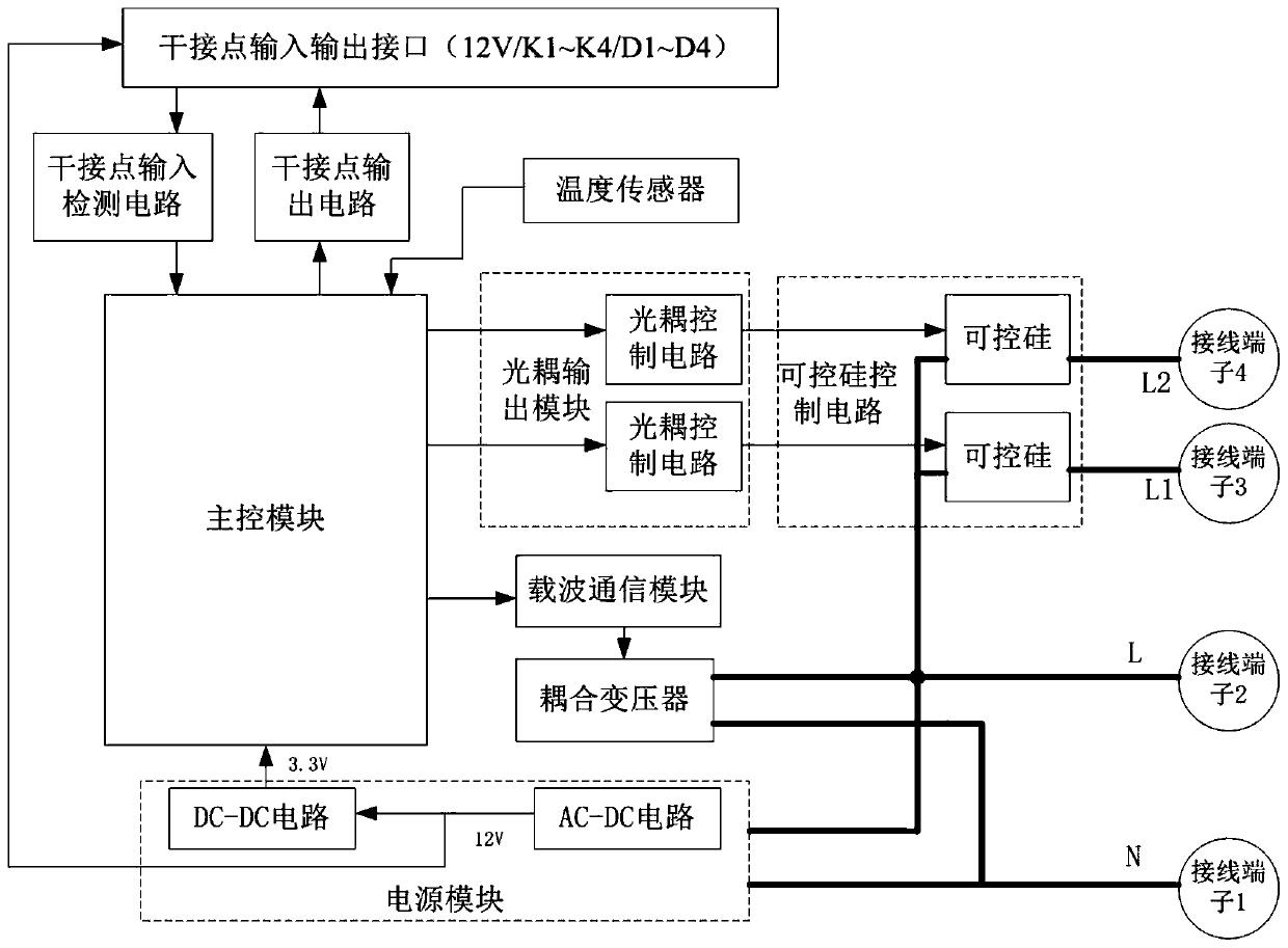
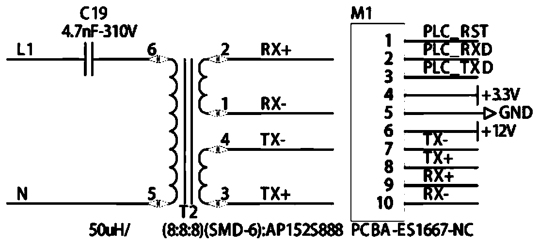
[0034] Such as figure 1 As shown, the embodiment of the present invention provides a dry contact switch based on HPLC communication, including a control circuit arranged on the main board, and the control circuit includes a main control module, a power supply module, a carrier communication module, a coupling transformer, and an optocoupler output Module and thyristor control circuit, the power mod...


PUM


Abstract

The invention relates to the field of smart home, and discloses a dry contact switch based on HPLC communication. The dry contact switch comprises a control circuit arranged on a mainboard, wherein the control circuit comprises a main control module, a power supply module, a carrier communication module, a coupling transformer, an optocoupler output module and a silicon controlled rectifier control circuit, the power supply module is used for converting external mains supply into direct-current voltage and then supplying power to the main control module, the carrier communication module, the optocoupler output module and the silicon controlled rectifier control circuit, the main control module is used for receiving dry contact signals and outputting signals to control the on-off of the optocoupler output module, the control end of the silicon controlled rectifier control circuit is connected with the output end of the optocoupler output module, the input end of the silicon controlled rectifier control circuit is connected with a mains supply live wire, the output end of the silicon controlled rectifier control circuit is connected with an electric terminal, the main control moduleis connected with the carrier communication module, and the carrier communication module is in communication connection with a mains supply power line through the coupling transformer. According to the invention, a zero line and live line access mode is adopted, compatibility is good, the requirement for a lamp is low, and the phenomena of slight lighting and flickering of a single-live-line switch are avoided.

Description

technical field [0001] The invention relates to the field of smart home, in particular to a dry contact switch based on HPLC communication. Background technique [0002] With the continuous development of smart home technology, smart switches are becoming more and more common in places such as homes and hotels. The existing smart switches mainly include single live wire access and zero live wire access. The single live wire smart switch only needs to connect a single live wire without the need for a neutral wire, and realizes the control of the lamp by controlling the on and off of the live wire; the zero live wire intelligent The switch needs to connect the neutral and live wires, and realize the control of the lamps by controlling the on and off of the live wires. Existing smart homes mainly transmit information through wireless communication and wired communication to realize intelligent control of places such as homes and hotels. Wireless communication mainly includes B...

Claims


Application Information

Patent Timeline
Patent Type & Authority Applications(China)
IPC IPC(8): G05B19/042H04B3/54
CPCG05B19/0428G05B2219/2642H04B3/54
Inventor 崔健左太祥李鹏
Owner QINGDAO DONGRUAN ZAIBO INTELLIGENT ELECTRONICS
Learn More