A component for automatic locking of a rotating shaft

An automatic locking and rotating shaft technology, which is applied to the parts, pivots, and pivot connections of lighting devices, can solve the problems of limited rotation angle of lamps and lamps that cannot be automatically locked, and achieve the effect of improving the swing range

Active Publication Date: 2021-11-02
HANGZHOU MEARI TECH CO LTD
View PDF9 Cites 0 Cited by
  • Summary
  • Abstract
  • Description
  • Claims
  • Application Information

AI Technical Summary

Problems solved by technology

[0003] At present, there are also some lamps that are installed on the X-axis rotating block through the rotation of the first U-shaped seat. For example, the application number: 201910369355.0, which discloses a rotating and lifting LED floodlight. The X-axis fixing bolt of the block, by adjusting the X-axis fixing bolt to adjust the locking of the lamp, the swing of the lamp can only swing in the direction of the X-axis or the Y-axis, and the rotation angle of the lamp is too limited
At the same time, the lamp cannot be locked automatically, and the fixing bolt needs to be manually adjusted to lock the position of the lamp

Method used


Image

  • A component for automatic locking of a rotating shaft
  • A component for automatic locking of a rotating shaft
  • A component for automatic locking of a rotating shaft

Examples


Embodiment 1

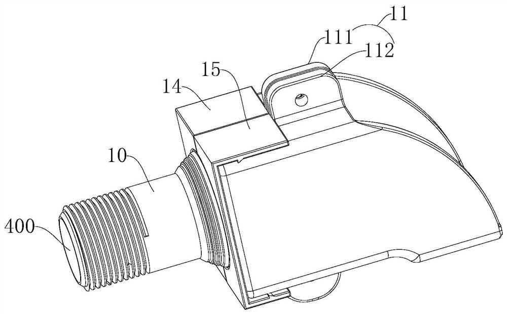
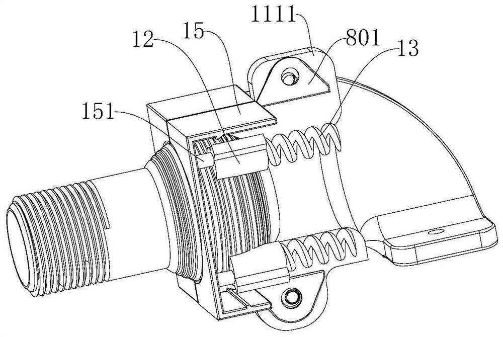
[0040] A component that automatically locks the rotating shaft, such as Figure 1-11 As shown, it includes a rotating shaft 10 and a fixed seat 11. The end of the fixed seat 11 is provided with a spherical cavity 110 along the axial direction. The rotating shaft 10 includes a spherical shaft head 101, and the shaft head 101 is installed in the cavity. 110 and axially locked on the fixed base 11 , the shaft head 101 can rotate in the cavity 110 , and the shaft head 101 rotates, so that the rotating shaft 10 rotates. The fixed seat 11 includes a first fixed seat 111 and a second fixed seat 112, the first fixed seat 111 and the second fixed seat 112 are assembled to form a cavity 110, that is, the first fixed seat 111 is provided with a half cavity, and the second fixed seat 111 The seat 112 is also provided with a half cavity, the half cavity on the first fixed seat 111 is combined with the half cavity on the second fixed seat 112 to form the cavity 110, the first fixed seat 111...

Embodiment 2

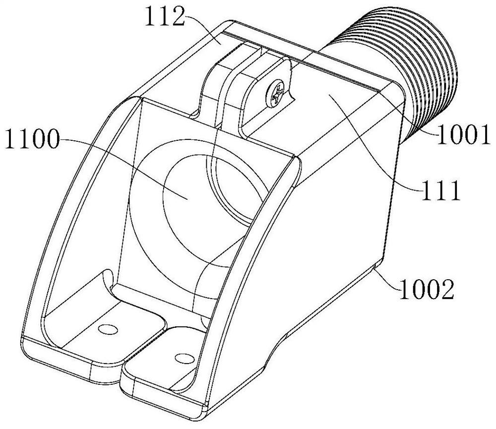
[0049] Embodiment 2 has basically the same features as Embodiment 1, except that the first fixing base 111 and the second fixing base 112 are respectively provided with a first through groove 1114 and a second through groove 1124, and the first through groove 1114 and the second through groove The grooves 1124 are all arc grooves. When the first fixed seat 111 and the second fixed seat 112 are fixed, the first through groove 1114 and the second through groove 1124 are synthesized into a channel 1100 communicating with the cavity 110, and the channel 1100 is cylindrical. The other end of 1100 passes through the fixing seat 11 . Lines such as signal lines or power lines are connected to other devices through the channel 1100 .

Embodiment 3

[0051] Embodiment 3 has basically the same features as Embodiment 1. The difference is that a first connecting plate 1115 extends from the side of the first fixing seat 111 away from the cavity 110, and the lower end of the first connecting plate 1115 is bent vertically inward to form a first fixing plate. plate 1116, the first fixed plate 1116 is provided with threaded holes connected with external equipment; the second fixed seat 112 extends away from the side of the cavity 110 with a second connecting plate 1125, and the lower end of the second connecting plate 1125 is folded vertically inward The second fixing plate 1126 is formed by bending, and the second fixing plate 1126 is provided with threaded holes for connecting with external equipment. Both the first connecting plate 1115 and the second connecting plate 1126 are arc-shaped connecting plates.


PUM


Abstract

The invention relates to a connecting part of a lamp, and discloses a component for automatically locking a rotating shaft, which includes a rotating shaft and a fixing seat. The end of the fixing seat is provided with a spherical cavity along the axial direction, and the rotating shaft includes a spherical shaft head. , the shaft head is installed in the cavity and axially locked on the fixed seat; the fixed seat includes a first fixed seat and a second fixed seat, the first fixed seat and the second fixed seat are assembled to form a cavity, the first fixed seat and the second fixed seat Mounting holes are arranged on the ends of the two fixing seats, and the upper end of the mounting holes communicates with the cavity, and a locking head is snapped and connected in the mounting holes, and a spring is installed between the locking head and the bottom of the mounting hole, and the locking head Pressed against the shaft head by a spring. The lamp is installed on the connecting piece, and the rotating shaft can rotate circumferentially in the cavity to improve the swing range of the lamp. Because the locking head is installed in the connecting piece, when people swing the rotating shaft to the designated position, the locking head can be pressed on the shaft head by the spring, so that the automatic locking of the rotating shaft is realized.

Description

technical field [0001] The invention relates to a connecting part of a lamp, in particular to a component for automatically locking a rotating shaft. Background technique [0002] The existing lighting and camera shafts basically adopt the handle tightening type, first unscrew the handle, so that the first tooth and the second tooth are loosened, and people can adjust the swing angle of the shaft, thereby adjusting the swing angle of the lamp. After the angle of the lamp is adjusted, people only need to tighten the handle, and the handle will mesh the first tooth with the second tooth, so as to realize the positioning function of the rotating shaft. [0003] At present, there are also some lamps that are installed on the X-axis rotating block through the rotation of the first U-shaped seat. For example, the application number: 201910369355.0, which discloses a rotating and lifting LED floodlight. The X-axis fixing bolt of the block, by adjusting the X-axis fixing bolt to ad...

Claims


Application Information

Patent Timeline
Patent Type & Authority Patents(China)
IPC IPC(8): F16C11/06F16C11/10F16M11/14F16M11/16F21V17/16F21V14/02F21V15/04F21V21/08
CPCF16C11/0614F16C11/10F16M11/14F16M11/16F16M2200/024F21V14/02F21V15/04F21V17/164F21V21/08
Inventor 占雪霏
Owner HANGZHOU MEARI TECH CO LTD
Why Eureka
Try Eureka