Automatic steering greenhouse suspension type rail transport vehicle system and working method thereof
A technology for rail transport vehicles and automatic steering, applied in the field of rail transport vehicles, can solve the problems of affecting the transport of transport vehicles, unable to automatically change rails, low work efficiency, etc., and achieve the effect of being conducive to cleaning and avoiding occupation of ground rails
- Summary
- Abstract
- Description
- Claims
- Application Information
AI Technical Summary
Problems solved by technology
Method used
Image
Examples
Embodiment 1
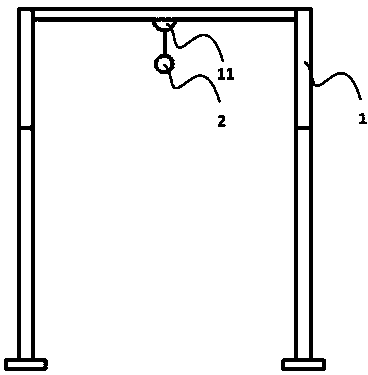
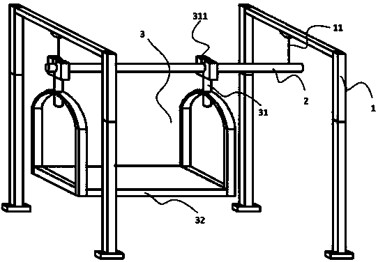
[0060] refer to Figure 1-4as an example.
[0061] An automatic steering greenhouse suspension rail transport vehicle system, comprising: a support column 1, a track beam 2, a transport vehicle 3, and a software central control device 4.
[0062] The support columns 1 are distributed on the transportation track, the top of the support column 1 is provided with a suspension structure 11, the track beam 2 is fixedly connected with the suspension structure 11, and the track beam 2 is distributed along the transportation track.
[0063] The support column 1 is set in the factory area, and the frame of the track beam 2 is erected. The support column 1 can be in the form of a door, and the suspension structure 11 is fixed on the top of the support column 1 . The suspension structure 11 is used to support the connection between the track beam 2 and the support column 1 . Track beams 2 are laid on the way of the transport path.
[0064] The transport vehicle 3 includes a suspensio...
Embodiment 2
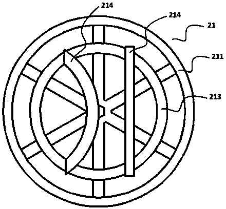
[0084] refer to Figure 5-7 as an example.
[0085] This embodiment is basically the same as the first embodiment above, except that, as a preferred mode of this embodiment, the car body 32 includes a loading and unloading shaft 321 , a displacement device 322 , and a displacement driving motor 323 .
[0086] The loading and unloading shafts 321 are cylindrical and arranged horizontally. Several loading and unloading shafts 321 are on the same horizontal plane and parallel to each other. One end of the loading and unloading shafts 321 is connected to the displacement device 322 . The displacement device 322 drives the loading and unloading shaft 321 to displace laterally.
[0087] The columnar loading and unloading shaft 321 cooperates with the tray flower pot, and the loading and unloading shaft 321 is inserted into the groove of the tray flower pot, and the loading and unloading shaft 321 can be lifted to lift the tray flower pot.
[0088] The displacement device 322 drive...
Embodiment 3
[0106] refer to Figure 8 as an example.
[0107] This embodiment is basically the same as the first embodiment above, the difference is that, as a preferred mode of this embodiment, a distance sensor 5 is provided at the bottom of the loading and unloading shaft 321, and the distance sensor 5 monitors the loading and unloading shaft 321 The distance between the bottom and the ground. The distance sensor 5 is connected to the software central control device 4, and the software central control device 4 determines whether the ground is empty according to the distance data detected by the distance sensor 5.
[0108] The distance sensor 5 monitors the distance between the bottom of the loading and unloading shaft 321 and the ground. When there are no other items on the ground, the distance to the ground is a fixed value. If there are other items on the ground, the distance will change.
[0109] The software central control device 4 can judge whether an object has been placed on ...
PUM
 Abstract
Description
Claims
Application Information
 - R&D Engineer
- R&D Manager
- IP Professional
- Industry Leading Data Capabilities
- Powerful AI technology
- Patent DNA Extraction
Browse by: Latest US Patents, China's latest patents, Technical Efficacy Thesaurus, Application Domain, Technology Topic, Popular Technical Reports.
© 2024 PatSnap. All rights reserved.Legal|Privacy policy|Modern Slavery Act Transparency Statement|Sitemap|About US| Contact US: help@patsnap.com


