High-viscosity material sampling structure and method

A high-viscosity, high-material technology, applied in the direction of sampling, sampling device, valve housing structure, etc., can solve the problems of small sampler pipeline diameter, condensation blockage, splashing and scalding of high-viscosity materials, etc., to achieve safe sampling and not easy to condense blockage Effect

Inactive Publication Date: 2020-08-11
SHANXI LUAN COAL BASED CLEAN ENERGY
View PDF0 Cites 1 Cited by
  • Summary
  • Abstract
  • Description
  • Claims
  • Application Information

AI Technical Summary

Problems solved by technology

For the transportation of high-viscosity materials, it is necessary to rely on the flow rate brought by the high pressure difference and the high material temperature. During the sampling operation, there are two risks from high pressure and high temperature. High-temperature and high-pressure high-viscosity materials are prone to splashing and scalding. Moreover, the traditional sampler pipeline has a small diameter, which is prone to condensation and blockage

Method used


Image

  • High-viscosity material sampling structure and method
  • High-viscosity material sampling structure and method
  • High-viscosity material sampling structure and method

Examples


Embodiment Construction

[0034] In order to make the object, technical solution and advantages of the present invention clearer, the invention will be further described in detail below in conjunction with the accompanying drawings.

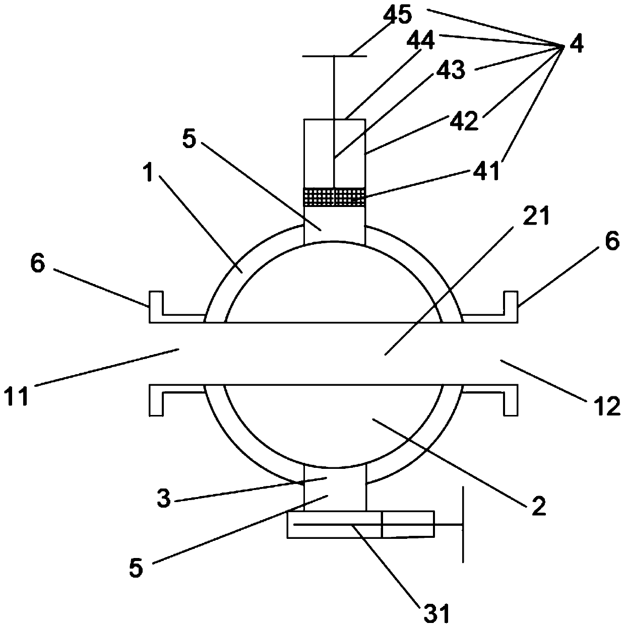
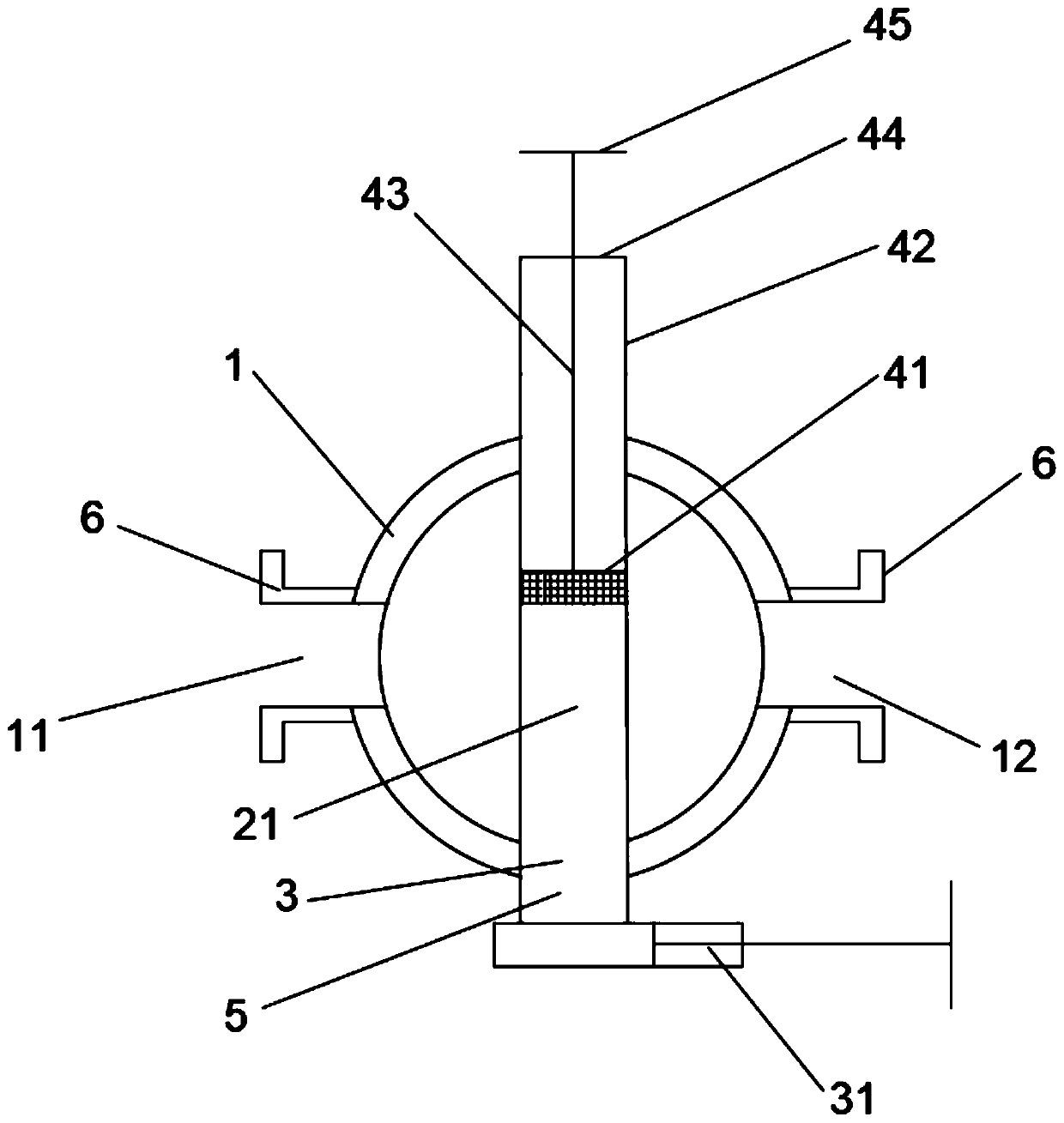
[0035] Such as Figure 1-Figure 3 As shown, the embodiment of the high-viscosity material sampling structure disclosed by the present invention includes a ball valve body 1, a ball valve core 2 and a control structure. Matching, the ball valve core 2 rotates and fits in the ball valve body 1, the control structure is connected with the ball valve core 2, the ball valve body 1 has a medium inlet 11 and a medium outlet 12, the medium inlet 11 communicates with the upstream high-viscosity material delivery pipeline, and the medium outlet 12 communicates with the downstream high-viscosity material delivery pipeline. The ball valve core 2 has a medium flow channel 21 with two ends running through the ball valve core 2. The ball valve body 1 also has a sampling port 3 and a pus...


PUM


Abstract

The invention discloses a high-viscosity material sampling structure, which comprises a ball valve body, a ball valve core and a control structure, wherein the ball valve body is arranged on the high-viscosity material conveying pipeline; the ball valve core is matched with an inner cavity of the ball valve body; the ball valve core is rotationally matched in the ball valve body; the control structure is in transmission connection with the ball valve core; the ball valve body is provided with a medium inlet and a medium outlet; a medium flow channel with the two ends penetrating through the ball valve core is formed in the ball valve core;the ball valve body is further provided with a sampling opening and a pushing and pressing device; the sampling port is arranged between the medium inletand the medium outlet; a valve is arranged at the sampling port; the pushing and pressing device is arranged opposite to the sampling port; a pressure relief space is arranged between the ball valvebody and the valve and / or between the ball valve body and the pushing and pressing device, and the valve and / or the pushing and pressing device are / is communicated with an inner cavity of the ball valve body through the corresponding pressure relief space. The invention further discloses a sampling method adopting the high-viscosity material sampling structure. According to the high-viscosity material sampling structure and method, sampling is safe and efficient, and coagulation and blockage are not likely to happen.

Description

technical field [0001] The invention relates to the technical field of pipeline sampling, in particular to a high-viscosity material sampling structure and method. Background technique [0002] In the daily production process, it is often necessary to take samples to test the materials conveyed in the pipeline. For the transportation of high-viscosity materials, it is necessary to rely on the flow rate brought by the high pressure difference and the high material temperature. During the sampling operation, there are two risks from high pressure and high temperature. High-temperature and high-pressure high-viscosity materials are prone to splashing and scalding. Moreover, the traditional sampler pipeline has a small diameter and is prone to condensation and blockage. Contents of the invention [0003] The invention aims to provide a high-viscosity material sampling structure and method, which is safe and efficient in sampling, and is not prone to condensation and blockage....

Claims


Application Information

Patent Timeline
IPC IPC(8): G01N1/20F16K11/087F16K27/06F16K3/02F16K3/314
CPCF16K3/0281F16K3/314F16K11/0873F16K27/067G01N1/2035G01N2001/2057
Inventor 任超苗路斌李陆山连雅申惠刘凯
Owner SHANXI LUAN COAL BASED CLEAN ENERGY
Why Eureka
Try Eureka