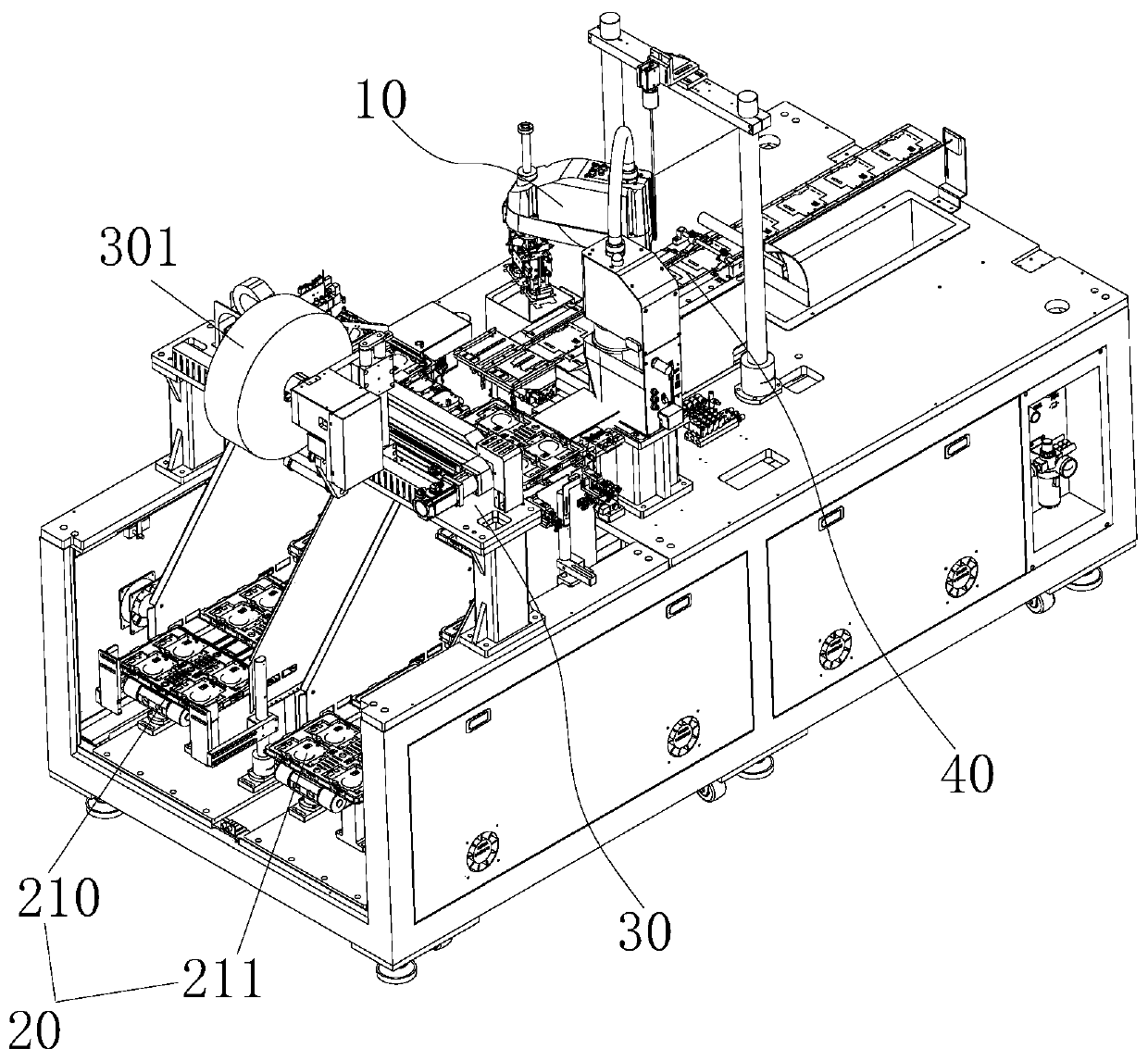
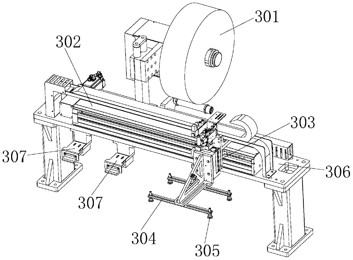
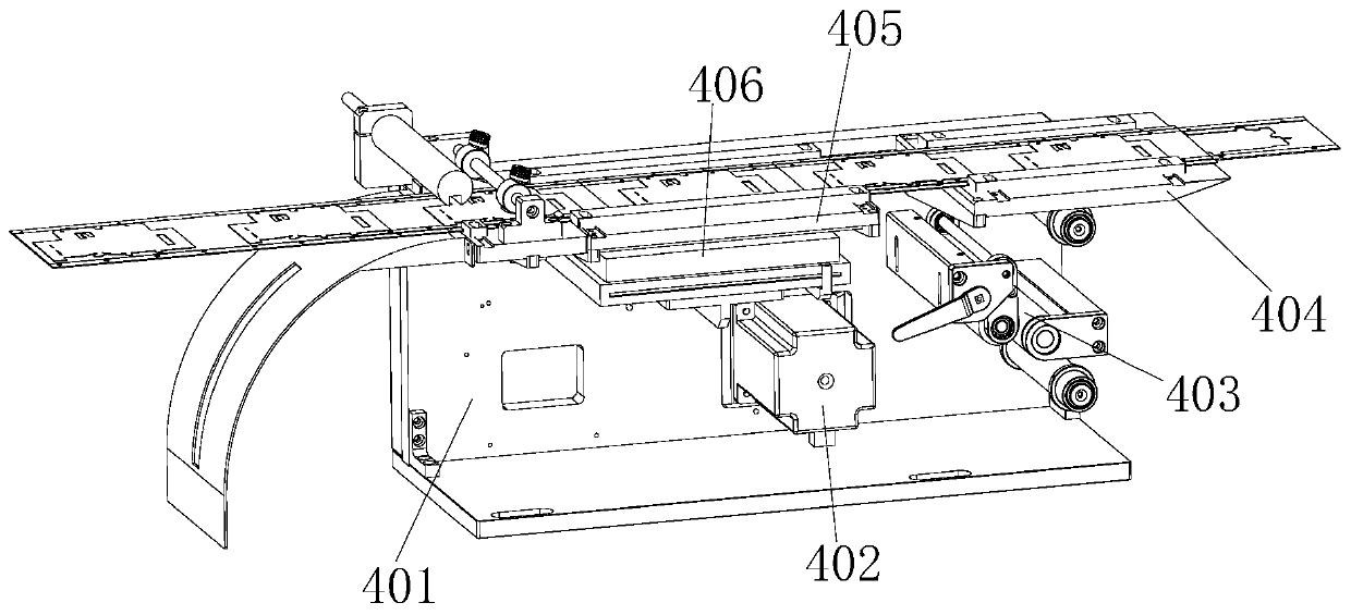
Tray collecting machine

A material tray and empty tray technology, which is applied in the field of material transfer equipment, can solve the problems of large area of ​​​​the tiled loading and unloading truck, the large stroke span of the reclaiming manipulator, and the large area of ​​​​the tiled truck. Small footprint, simple structure, continuous feeding and unloading effect

Pending Publication Date: 2020-08-11
深圳市罗博威视科技有限公司
View PDF0 Cites 0 Cited by
  • Summary
  • Abstract
  • Description
  • Claims
  • Application Information

AI Technical Summary

Problems solved by technology

[0003] The existing tiled loading and unloading trucks on the market have the following defects: the tiled loading and unloading trucks occupy a large area; after the inspection of the products placed on the first tray is completed, they need to be placed on other trays by the reclaiming manipulator. The material tray is separated from the undetected products of the first tray. Because the tiled material trolley occupies a large area, it is easy to cause a large stroke span of the reclaiming manipulator and a complicated structure.

Method used


Image

  • Tray collecting machine
  • Tray collecting machine
  • Tray collecting machine

Examples


Embodiment Construction

[0027] The present invention will be further described below in conjunction with the accompanying drawings and embodiments.

[0028] The idea, specific structure and technical effects of the present invention will be clearly and completely described below in conjunction with the embodiments and accompanying drawings, so as to fully understand the purpose, features and effects of the present invention. Apparently, the described embodiments are only some of the embodiments of the present invention, rather than all of them. Based on the embodiments of the present invention, other embodiments obtained by those skilled in the art without creative efforts belong to The protection scope of the present invention. In addition, all the connection / connection relationships involved in the patent do not simply refer to the direct connection of components, but mean that a better connection structure can be formed by adding or reducing connection accessories according to specific implementat...


PUM


Abstract

The invention discloses a tray collecting machine. The tray collecting machine comprises a feeding and discharging mechanism, a carrying mechanism, a mechanical arm and an attaching flow channel mechanism, wherein the carrying mechanism is located above the feeding and discharging mechanism and used for transferring material trays of a feeding mechanism to an empty tray discharging mechanism; anda material belt wheel used for providing a material belt for the attaching flow channel mechanism is arranged above the carrying mechanism, the mechanical arm is located on one side of the attaching flow channel mechanism, and the mechanical arm is used for transferring products in the material trays to the material belt of the attaching flow channel mechanism. The tray collecting machine has thebeneficial effects that the tray collecting machine can achieve automatic feeding and discharging of the material trays, and the feeding and discharging efficiency and the automation degree are improved.

Description

technical field [0001] The invention relates to the technical field of material transfer equipment, and more specifically, the invention relates to a closing machine. Background technique [0002] The current general loading and unloading method of trays (also known as trays) on the market is mainly flat, and its main structure is a tray upper level, a tray lower level placed in parallel, and the transfer tray passes through a horizontal It is realized by moving the take-and-close manipulator. [0003] The existing tiled loading and unloading trucks on the market have the following defects: the tiled loading and unloading trucks occupy a large area; after the inspection of the products placed on the first tray is completed, they need to be placed on other trays by the reclaiming manipulator. The material tray is separated from the undetected products of the first tray. Because the tiled material trolley occupies a large area, it is easy to cause a large stroke span of the r...

Claims


Application Information

Patent Timeline
Patent Type & Authority Applications(China)
IPC IPC(8): B65G47/74B65G47/91B65B35/16B65B15/04B65B57/00
CPCB65B15/04B65B35/16B65B57/00B65G47/74B65G47/912B65G2201/0258
Inventor 胡彦潮余太平李欣龙许朋飞
Owner 深圳市罗博威视科技有限公司
Why Eureka
Try Eureka