Automatic rotor packaging device and packaging method thereof
A technology of automatic packaging and equipment, which is applied in the direction of packaging, item rotation and wrapping, etc., and can solve the problem that the wrapping paper cannot be cut.
- Summary
- Abstract
- Description
- Claims
- Application Information
AI Technical Summary
Problems solved by technology
Method used
Image
Examples
Embodiment 1
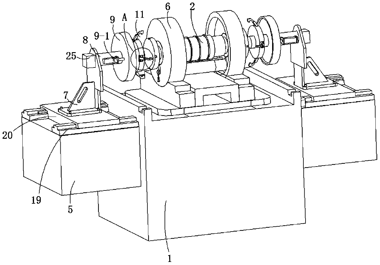
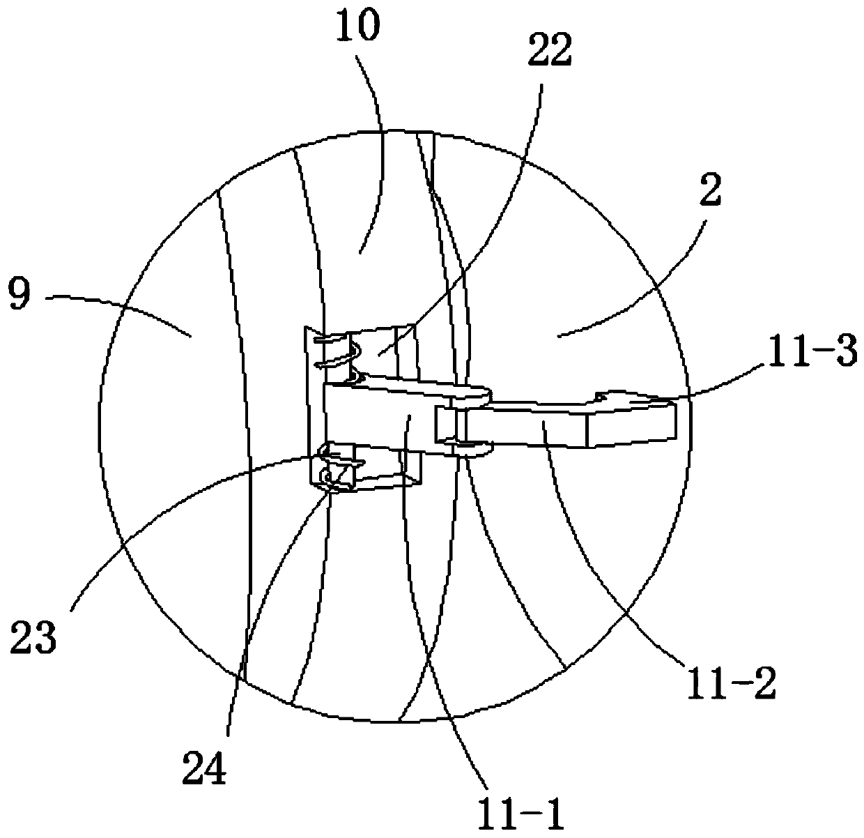
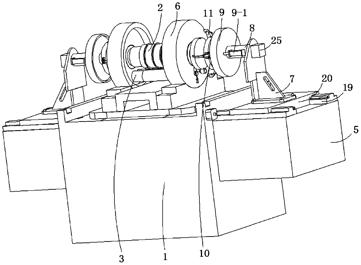
[0043] refer to Figure 1-4 , a rotor automatic packaging equipment and packaging method thereof, comprising a packaging table 1, a motor rotor 2, a wrapping paper 3, a friction roller 4, the wrapping paper 3 is specifically wound on a wrapping paper reel, and the side wall of the packaging table 1 is provided with Symmetrical workbench 5, the top of packaging table 1 is provided with two symmetrically distributed installation support plates 6, and the motor rotor 2 is rotatably arranged on the top of the installation support plate 6; the top of workbench 5 is slidingly provided with support seat 7, supporting The top of the seat 7 is rotatably connected with a rotating column 8, and the side wall of the rotating column 8 is slidably connected with a compression cover 9, and one end of the rotating column 8 away from the support seat 7 is fixedly provided with a fixed plate 10, and the side wall of the fixed plate 10 is provided with a circumferential Distributed clamping rods...
Embodiment 2
[0048] refer to Figure 1-4 , Figure 11 , Figure 12 , is basically the same as Embodiment 1, furthermore, the outer wall of the support seat 7 is provided with a driving motor 25, and the rotating column 8 is fixed on the rotating shaft at the output end of the driving motor 25, thereby utilizing the driving motor 25 to drive the rotating column 8 to rotate .
[0049] The side wall of the installation support disc 6 is provided with a through hole 26 for the telescopic movement of the wrapping paper 3, and the outer end of the wrapping paper 3 is provided with a shaft sleeve 27 as for the installation support disc 6, and the side wall of the installation support disc 6 is also provided with a drive. The adjusting cylinder 28 that moves the wrapping paper 3, the piston rod at the output end of the adjusting cylinder 28 is fixedly connected with the bushing 27, and the adjusting cylinder 28 pushes the bushing 27 through the piston rod at the output end, that is, pushes the w...
Embodiment 3
[0052] refer to Figure 1-10 , is basically the same as Embodiment 2, furthermore, the turning mechanism 17 includes a rotating ring 17-1, a connecting rod 17-2, and a smoothing roller shaft 17-3, and the rotating ring 17-1 is rotated and set on the limit rod 14- 2, the power spring 16 is fixed between the rotating ring 17-1 and the limit block 14-3, the connecting rod 17-2 is fixedly connected with the rotating ring 17-1, and the cutting blade 18 is fixed on the connecting rod 17 -2 side walls, the side of the connecting rod 17-2 away from the cutting blade 18 is fixed with a connecting column 29, and the smoothing roller shaft 17-3 is rotated and arranged on the connecting column 29. When the turning mechanism 17 is in a vertical state, the The flat roller shaft 17-3 can be in contact with the motor rotor 2 on which the wrapping paper 3 is attached, so that the wrapping paper 3 can be attached to the surface of the motor rotor 2 stably.
[0053] The side wall of the connect...
PUM
 Abstract
Description
Claims
Application Information
 - R&D
- Intellectual Property
- Life Sciences
- Materials
- Tech Scout
- Unparalleled Data Quality
- Higher Quality Content
- 60% Fewer Hallucinations
Browse by: Latest US Patents, China's latest patents, Technical Efficacy Thesaurus, Application Domain, Technology Topic, Popular Technical Reports.
© 2025 PatSnap. All rights reserved.Legal|Privacy policy|Modern Slavery Act Transparency Statement|Sitemap|About US| Contact US: help@patsnap.com


