


Quick Research
Generate reliable direction feasibility study reports for your R&D in just a few steps.

Technical Q&A
Discover and master advanced knowledge NOW. Basics, ideas, possibilities, all at once.

Find Solutions
As an expert in R&D theories, this can generate solutions to your technical problems instantly.

Evaluate Feasibility
Analyze your overall solution with one click, know your potential R&D risks in advance.

Monitor Landscape
Get weekly tech updates, stay abreast of the latest tech innovations and key insights.
Flight method and flight device
A technology of a flying device and an electromagnetic device, applied in the field of flight, can solve the problems that the electric driving wheel device cannot be observed nearby, sampling, and the electric driving wheel device is prone to accidents, etc.
- Summary
- Abstract
- Description
- Claims
- Application Information
AI Technical Summary
Problems solved by technology
Method used
Image

Examples
Embodiment 1
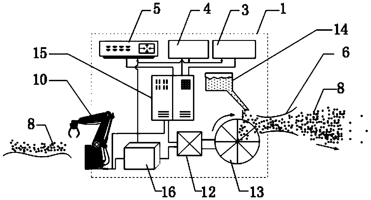
[0042] A lunar surface flying device, such as figure 1 As shown, the flight body 1 is included, and the flight body 1 includes a power supply 16 , a high-speed motor 12 , an impeller 13 and a lunar soil storage container 14 .
[0043] In the working state, the power supply 16 supplies power to the high-speed motor 12, and the high-speed motor 12 works to drive the impeller 13 to rotate at a high speed. The lunar soil 8 falls from the lunar soil storage container 14 to the impeller 13, is accelerated by the high-speed rotating impeller 13, and is thrown out through the nozzle 6. , the reaction force generated overcomes the gravitational force of the moon and drives the flying device to take off on the moon.
[0044] The flight device also includes Probe A3 and Probe B4 for detection research.
[0045] The flying device also includes a communicator 5 for communication.
[0046] The flying device also includes a central controller 15 for coordinated control of the entire flying d...
Embodiment 2
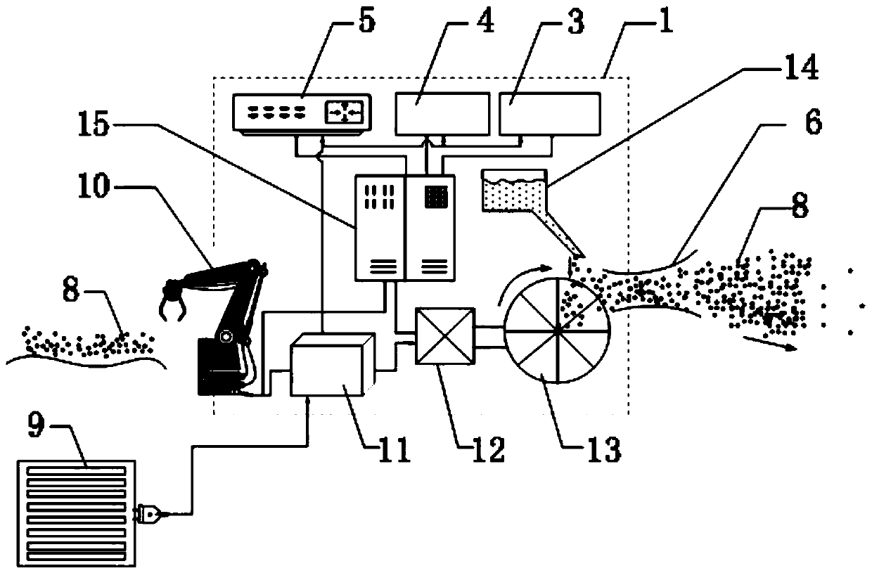
[0049] A lunar surface flying device, such as figure 2 As shown, a flight body 1 is included, and the flight body 1 includes a power supply 11 , a high-speed motor 12 , an impeller 13 and a lunar soil storage container 14 .
[0050] During the working state, the power supply 11 is powered by a high-speed motor, and the high-speed motor 12 works to drive the impeller 13 to rotate at a high speed. The lunar soil 8 falls from the lunar soil storage container 14 to the impeller 13, is accelerated by the high-speed rotating impeller 13, and is thrown out through the nozzle 6. The generated reaction force overcomes the gravitational force of the moon and drives the flying device to take off on the moon surface.
[0051] In this embodiment, the power source 11 is a storage battery, and the onboard storage battery can be quickly charged by the lunar solar power station 9 if necessary.
[0052] In addition, in this embodiment, the lunar soil 8 is grabbed by the lunar soil grabbing an...
Embodiment 3
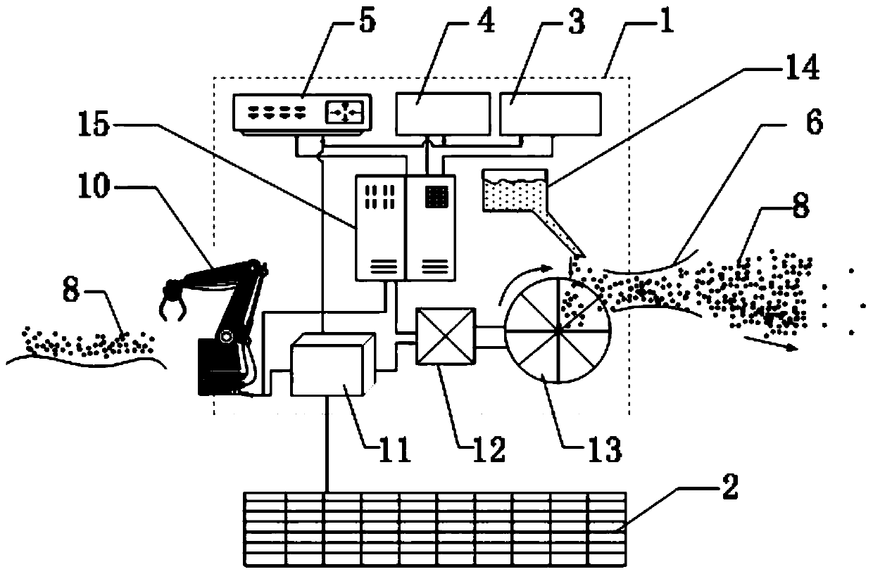
[0057] In this embodiment, the structure of the lunar surface flight device is basically the same as that of Embodiment 2, the difference is that the solar power station 9 is replaced by the solar panel 2, and the solar panel 2 is arranged on the flight device, so when the power is insufficient, the flight The device charges the accumulator 11 through the solar panel 2 .
[0058] In this embodiment, the flying method of the flying device is the same as that in Embodiment 1.
PUM
 Abstract
Description
Claims
Application Information
 - R&D Engineer
- R&D Manager
- IP Professional
- Industry Leading Data Capabilities
- Powerful AI technology
- Patent DNA Extraction
Browse by: Latest US Patents, China's latest patents, Technical Efficacy Thesaurus, Application Domain, Technology Topic, Popular Technical Reports.
© 2024 PatSnap. All rights reserved.Legal|Privacy policy|Modern Slavery Act Transparency Statement|Sitemap|About US| Contact US: help@patsnap.com