Eureka AIR delivers breakthrough ideas for toughest innovation challenges, trusted by R&D personnel around the world.

Controllable fuse, fuse assembly and control method

A fuse and fusing technology, applied in the direction of relays, electrical components, emergency protection devices, etc., can solve the problems of prolonging research and development time, damage to smart devices, inconvenient use, etc., and achieve the effect of precise overcurrent protection

Active Publication Date: 2020-08-07
NANJING SART SCI & TECH DEV
View PDF9 Cites 0 Cited by
  • Summary
  • Abstract
  • Description
  • Claims
  • Application Information

AI Technical Summary

Problems solved by technology

As a result, smart devices cause unnecessary damage, prolong the time of research and development, and increase the cost of research and development
However, the fuses in the prior art are all fixed fusing current devices, and at the same time need to manually adjust the current, and once destroyed, they cannot continue to be used, and when multiple fuses are required in the same circuit, each individual fuse needs to be broken. It is very inconvenient to use it in parallel. For example, if an overcurrent occurs in the battery system of the smart device and the fuse blows, the smart device will be in a stagnant state, wasting resources

Method used


Image

  • Controllable fuse, fuse assembly and control method
  • Controllable fuse, fuse assembly and control method

Examples


Embodiment 1

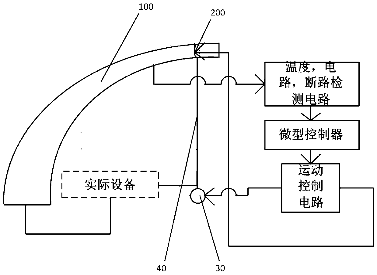
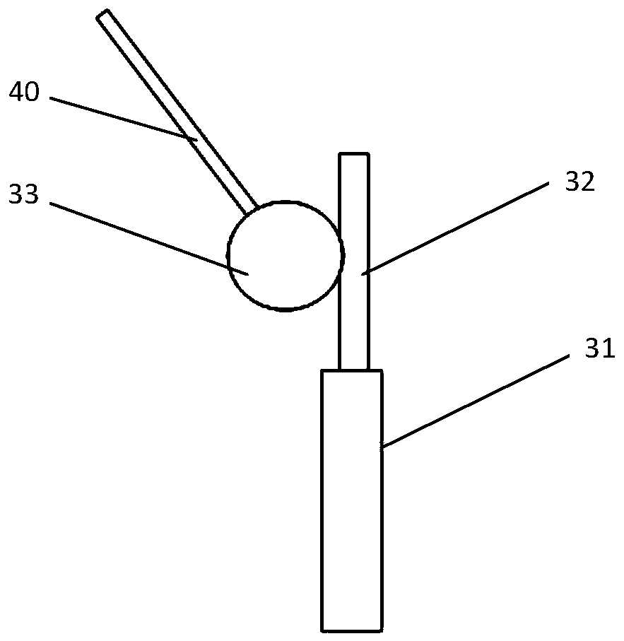
[0021] Please combine figure 1 As shown, this embodiment discloses a fuse assembly, which includes a controllable fuse, a motion controller circuit, a microcontroller circuit and a detection circuit. The controllable fuse includes a fuse metal body 100 , a driving device, and an automatic terminal locking device 200 . The cross-sectional area of ​​the fuse metal body 100 gradually increases from one end of the fuse metal body 100 along the extending direction of the fuse metal body 100; the terminal locking device 200 is conductive, and serves as a terminal and an overcurrent protected device Make an electrical connection. One end of the fuse metal body 100 is used as another terminal to form an electrical connection with the device to be protected from overcurrent. When the fuse assembly is in use, the terminal locking device 200 is in contact with the fuse metal body 100 and moves back and forth along the extending direction of the fuse metal body 100 ; the driving device ...

Embodiment 2

[0029] This embodiment is the control method of the fuse assembly in the first embodiment above. After the controllable fuse is connected to the protected equipment at both ends, the current value signal detected by the detection circuit is transmitted to the control system. The control system controls the end locking device 200 to slide so that the fusing current reaches the set fusing requirement.

[0030] Set the temperature threshold of the fuse metal body. When the detection circuit detects that the current temperature value of the fuse metal body 100 is greater than the temperature threshold and the circuit is not broken, the automatic locking device 200 at the control end performs a loosening action to automatically break the circuit. After a period of time, it automatically locks The device 200 continues to lock the fuse metal body to connect the circuit so that the circuit can work normally. And when the automatic locking device 200 is locked on the same position of the...

Embodiment 3

[0035] Embodiment 3 provides a controllable fuse, which is an independent controllable fuse in Embodiment 1. The independent controllable fuse can be manufactured and used as a single product, including a fuse metal body 100, a drive The device and the terminal automatic locking device 200 realize the selection of different rated fusing currents. Since the controllable fuse in this embodiment is completely the same as the controllable fuse in Embodiment 1, details will not be repeated here.


PUM


Abstract

The invention relates to a controllable fuse and a fuse assembly. The controllable fuse comprises a fuse metal body, a driving device and a tail end automatic locking device. The assembly further comprises a motion controller circuit, a microcontroller circuit and a detection circuit. The cross section area of the fuse metal body is gradually increased from one end of the fuse metal body in the extension direction of the fuse metal body. And the tail end locking device is contacted with the fuse metal body at different positions, so that the rated current value of the fuse is adjusted. The detection circuit is arranged, so that the temperature value and the current value on the fuse metal body can be detected in real time, and whether the fuse metal body is in an open circuit state is alsodetected; the rated current value of the fuse is correspondingly adjusted by reasonably controlling the tail end automatic locking device to move, and a more accurate over-current protection effect is provided for protected electrical equipment. The invention also provides a control method of the fuse assembly.

Description

technical field [0001] The invention belongs to the technical field of electronic devices, in particular to a fuse and a component containing the fuse. Background technique [0002] Fuses are commonly used electrical components that play a protective role in circuits. Generally, when the fuse circuit is overloaded, the fuse will be heated by the fusing current to quickly fuse the fuse to disconnect the circuit to realize circuit protection. Generally, a fuse has its own rated current capacity, which is determined by the metal parts that make up the fuse. With the development and popularization of smart devices, smart devices use a large number of batteries, and the main circuit that provides power for smart devices is also convenient for the use of smart devices. In the main circuit of smart devices, the existing fuses that fuse the fuse by heating are used. Sometimes in order to better protect the circuit, two or more fuses need to be used in parallel. At the same time, t...

Claims


Application Information

Patent Timeline
IPC IPC(8): H01H85/055H01H47/02
CPCH01H85/055H01H47/02
Inventor 杨漫雪陈荣华娇丁晨晖
Owner NANJING SART SCI & TECH DEV
Why Eureka
Eureka Blog
Learn More