A kind of automatic replacement fuse, fuse assembly and control method
An automatic replacement and fuse technology, applied in electrical components, emergency protection devices, circuits, etc., can solve problems such as inability to guarantee replacement, different installation methods, inability to quickly and intelligently adjust or replace fuses, etc., to achieve accurate overcurrent protection. effect of effect
- Summary
- Abstract
- Description
- Claims
- Application Information
AI Technical Summary
Problems solved by technology
Method used
Image
Examples
Embodiment 1
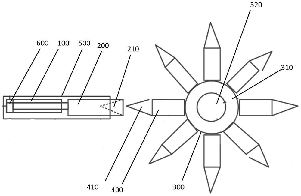
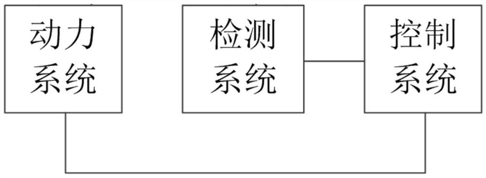
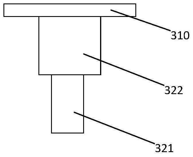
[0026] please combine figure 1 and figure 2 As shown, this embodiment discloses a fuse assembly, which includes an automatic fuse replacement, a power system, a detection system, and a control system. The automatic fuse replacement includes a push-pull rod 100 , a metal conductor connector 200 connected to the moving end of the push-pull rod 100 , a rotary connector 300 , several melts 400 mounted on the rotary connector 300 , a housing 500 , and a telescopic rod pusher 600 . The telescopic rod pusher 600 is used to push the telescopic rod 100 to extend or retract. The telescopic rod pusher 600 and the telescopic rod 100 are located in the casing, and the metal conductor connector 200 extends from the front end of the casing 600 . The rotary connector 300 is a conductor, and the rotary connector 300 includes a turntable 310 and a driving device 320 for driving the turntable 310 to rotate. The plurality of melts 400 are installed around the outer edge of the turntable 310 , ...
Embodiment 2
[0033] This embodiment is the control method of the fuse assembly in the above-mentioned first embodiment. In the control method, the push-pull rod 100 is pushed to make the metal conductor connector 200 contact and connect with a melt 400 . When the melt 400 is fused, the push-pull rod 100 is retracted, the turntable 310 of the rotary connector is rotated, the other unfused melt is rotated to the position facing the metal conductor connector 200, and the push-pull rod 100 is pushed to make the metal conductor The connector 200 is in contact with the unfused melt to complete the operation of replacing the melt.
[0034] Another optional way is: push the push-pull rod 100 to make the metal conductor connector 200 contact and connect with a melt 400; the detection system detects the current value passing through the melt 400 in real time and sets a comparison threshold, when the detected current When the value is higher than the comparison threshold, the push-pull rod 100 is con...
Embodiment 3
[0036] The third embodiment provides an automatic replacement fuse, which is an independent automatic replacement fuse in the first embodiment. The independent automatic replacement fuse can be manufactured and used as a product alone, and is controlled manually or automatically. The push-pull of the push-pull rod 100 and the rotation of the rotary connector 300 realize the selection of different fuses. Since the automatic replacement of the fuse in this embodiment is exactly the same as the automatic replacement of the fuse included in the first embodiment, it will not be repeated here.
PUM
 Abstract
Description
Claims
Application Information
 - R&D
- Intellectual Property
- Life Sciences
- Materials
- Tech Scout
- Unparalleled Data Quality
- Higher Quality Content
- 60% Fewer Hallucinations
Browse by: Latest US Patents, China's latest patents, Technical Efficacy Thesaurus, Application Domain, Technology Topic, Popular Technical Reports.
© 2025 PatSnap. All rights reserved.Legal|Privacy policy|Modern Slavery Act Transparency Statement|Sitemap|About US| Contact US: help@patsnap.com


