Photoelectric composite cable and forming method thereof

A photoelectric composite cable and optical unit technology, which is applied to power cables including optical transmission components, power cables, insulated cables, etc., and can solve the time-consuming and labor-intensive problems of taking out optical units

Active Publication Date: 2020-08-07
JIANGSU HENGTONG WIRE & CABLE TECH +1
View PDF8 Cites 1 Cited by
  • Summary
  • Abstract
  • Description
  • Claims
  • Application Information

AI Technical Summary

Problems solved by technology

[0003] The embodiment of the present application provides a photoelectric composite cable and its forming method, so as to improve the time-consuming and labor-intensive problem in the operation process of taking out the optical unit in the prior art

Method used


Image

  • Photoelectric composite cable and forming method thereof
  • Photoelectric composite cable and forming method thereof
  • Photoelectric composite cable and forming method thereof

Examples


Embodiment

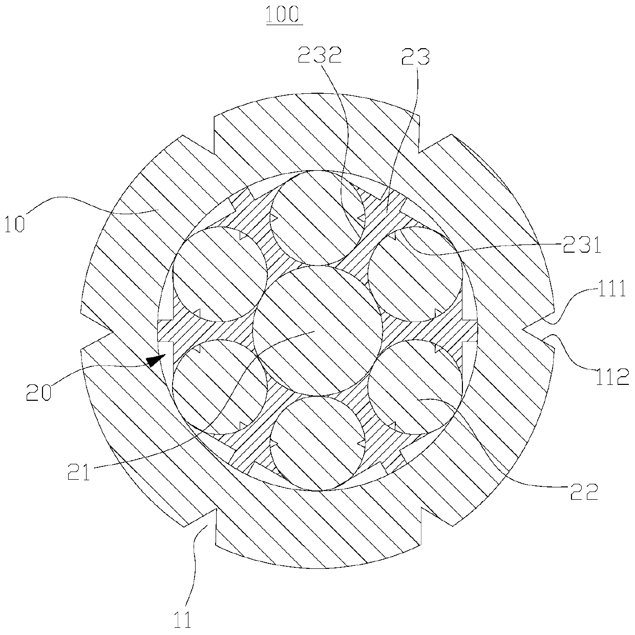
[0047] Such as figure 1 As shown, the embodiment of the present application provides a photoelectric composite cable 100, which includes an outer protective layer 10 and a core 20, and the outer protective layer 10 covers the outside of the core 20.

[0048] Wherein, the core body 20 includes an electric unit 21, a plurality of light units 22 and a plurality of filling bars 23. The plurality of light units 22 are distributed at circumferential intervals on the outside of the electric unit 21, and the distance between each adjacent two light units 22 A filling strip 23 is provided in the gap, and a first hand-tear notch 11 is provided on the outer surface of the outer protective layer 10 at a position corresponding to each filling strip 23.

[0049] In the above structure, a filling bar 23 is provided for every gap between two adjacent light units 22, and the filling bar 23 can ensure the relative position of the two adjacent light units 22. Since the position of the first-hand tear...


PUM


Abstract

The invention provides a photoelectric composite cable and a forming method thereof, and belongs to the field of photoelectric composite cables. The photoelectric composite cable comprises an outer protective layer and a core body, and the outer protective layer wraps the outer side of the core body, the core body comprises an electric unit, a plurality of optical units and a plurality of fillingstrips, the plurality of optical units are distributed on the outer side of the electric unit at intervals in the circumferential direction, one filling strip is arranged in a gap between every two adjacent optical units, and a first hand tearing notch is formed in the position, corresponding to each filling strip, of the outer surface wall of the outer protective layer. When the outer protectivelayer is torn through the first hand tearing notch, the filling strip is exposed, and the filling strip can be taken out from the torn notch. After the filling strip is taken out, the gap exists between the two optical units corresponding to the filling strip, the two optical units can move in the outer protective layer, and the optical units can be conveniently taken out from the torn notch. Theoptical units of the photoelectric composite cable are easy to take out, and time and labor are saved in the taking-out process.

Description

Technical field [0001] This application relates to the field of optoelectronic composite cables, and specifically to a photoelectric composite cable and a forming method thereof. Background technique [0002] The existing optoelectronic composite cable generally has a filling layer between the optical unit and the outer protective layer. After the outer protective layer is torn, the filling layer needs to be torn to take out the optical unit, which is troublesome and time-consuming and laborious. Summary of the invention [0003] The embodiments of the present application provide a photoelectric composite cable and a forming method thereof, so as to improve the problem of time-consuming and labor-intensive operation of taking out the optical unit in the prior art. [0004] In the first aspect, an embodiment of the present application provides a photoelectric composite cable, including an outer protective layer and a core, the outer protective layer covering the outside of the core; ...

Claims


Application Information

Patent Timeline
Patent Type & Authority Applications(China)
IPC IPC(8): H01B9/00H01B7/38H01B13/00G02B6/44
CPCH01B9/005H01B7/38H01B13/00G02B6/443
Inventor 楚广虎陆春良何剑姚福荣王晨王波徐盛祥
Owner JIANGSU HENGTONG WIRE & CABLE TECH
Why Eureka
Try Eureka