Multi-sample rapid replacement type scanning probe microscope

A scanning probe, multi-sample technology, applied in the field of scanning probe microscopy, can solve the problems of large thermal fluctuations, bulky, and reduced imaging quality, and achieve improved scanning imaging accuracy, convenient control signals, and consistent thermal fluctuations. Effect

Active Publication Date: 2020-08-07
NANJING UNIV OF INFORMATION SCI & TECH
View PDF10 Cites 1 Cited by
  • Summary
  • Abstract
  • Description
  • Claims
  • Application Information

AI Technical Summary

Problems solved by technology

However, the environment settings require a long time and careful preparation, which makes it necessary to pay a huge time and economic cost when replacing the sample.
[0003] In the prior art, there are patents that can realize large-scale scanning of samples, and the implementation method is to use multiple control signals to realize the movement of X and Y axes on the stage. For example, patents 201780082870.X and 201480077349.3 both involve large-scale sample scanning However, it does not involve a variety of sample scanning and sample replacement issues, and the way to realize the movement of the stage has the following defects: (1) In order to realize the movement in the X and Y directions, multiple drivers need to be added, thereby introducing more The noise source reduces the imaging quality; (2) the movement accuracy of the stage is limited, the bulky size leads to large thermal fluctuations, and the control movement process will introduce vibration, which is not good for scanning imaging; (3) the stage needs to be placed inside, The structure in the outer frame is complicated, so its thermal expansion coefficient and overall rigidity cannot be guaranteed in low temperature and strong magnetism;

Method used


Image

  • Multi-sample rapid replacement type scanning probe microscope
  • Multi-sample rapid replacement type scanning probe microscope
  • Multi-sample rapid replacement type scanning probe microscope

Examples


Embodiment 1

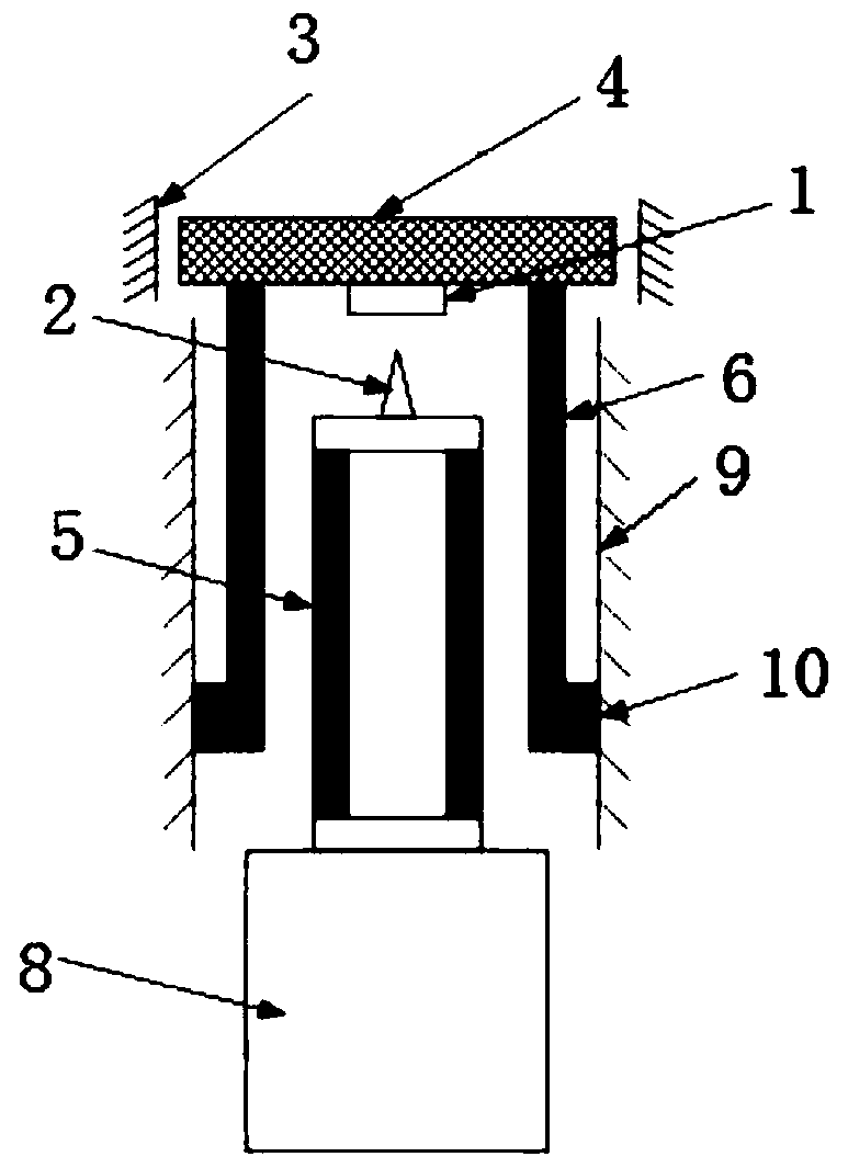
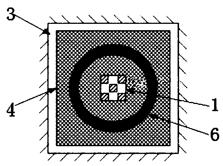
[0033] like Figure 1 to Figure 3 As shown, the braking motor pushes the scanning tube 5 and the probe 2 to approach (or move away from) the sample surface (Z direction), and the scanning tube 5 controls the probe 2 to perform two-dimensional scanning in the XY direction. The piezoelectric tube 6 and the scanning tube 5 belong to a nested relationship, and applying a spike signal to the piezoelectric tube can control the swing of the mass in the XY direction (equivalent to an inertial motor). The sample stage 1 is fixed on the mass block 4, such as figure 2 As shown, in the initial state (that is, when the mass block 4 is in the center of the XY limit device 3 ), the probe 2 is facing the sample at the center, which can be scanned and imaged. After scanning, the probe 2 is controlled to retreat a certain distance, and then the piezoelectric tube 6 is controlled to swing so that the mass block 4 drives the sample to move in the XY direction. This movement does not need to ca...

Embodiment 2

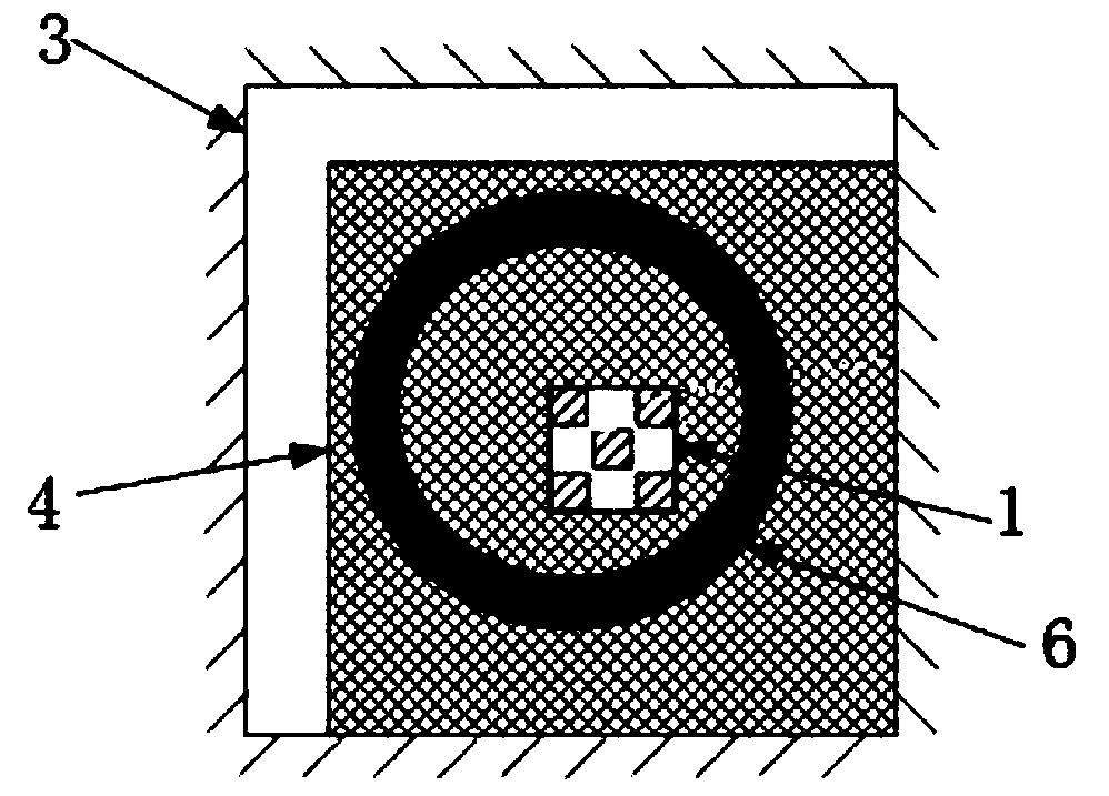
[0035] like Figure 4 As shown, on the basis of Embodiment 1, the positions of the probe 2 and the sample stage 1 are exchanged, the piezoelectric tube 6 drives the mass block 4 to move in the XY position, and the XY limit device 3 can make the probe 2 respectively align Five samples on the quasi-sample stage 1 (mass block 4 is in the center of the limit device in the initial state, and probe 2 is facing the central sample). During scanning, the scanning tube 5 applies a scanning signal to drive the sample to scan, and the probe 2 does not move during the scanning process.

Embodiment 3

[0037] like Figure 5 to Figure 7 As shown, on the basis of the first embodiment, the functions of the scanning tube 5 and the piezoelectric tube 6 are interchanged. The sample stage 1 is fixed on the mass block 4 connected with the piezoelectric tube 6 , and the probe 2 is fixed on the free end of the scanning tube 5 . The piezoelectric tube 6 controls the mass block 4 to perform inertial swinging in the XY direction, and the scanning tube 5 controls the probe 2 to scan, and the scanning of 5 samples can also be realized.


PUM


Abstract

The invention discloses a multi-sample rapid replacement type scanning probe microscope, which comprises a sample table, probes, an XY limiting device, a mass block, a scanning tube and a piezoelectric tube, and is characterized in that one of the sample table and the probes is arranged on the mass block, the other one is arranged at the free end of the scanning tube, and the probes are opposite to the middle position of the sample table in an initial state; the mass block is arranged in the XY limiting device, the mass block is installed at the top end of the piezoelectric tube, a peak signalis applied to the piezoelectric tube, and the mass block is driven to move in the XY direction in the XY limiting device by controlling the piezoelectric tube to swing; one of the scanning tube and the piezoelectric tube is connected with the driving mechanism, and the other is connected with the base. By moving the mass block in the two-dimensional direction, samples at the four corners and thecenter of the sample table can be accurately located under the scanning tube, and sequential scanning and rapid switching of various samples can be achieved.

Description

technical field [0001] The invention belongs to scanning probe microscope technology, in particular to a multi-sample quick-change scanning probe microscope. Background technique [0002] Scanning probe microscope is a microscope that uses a probe to scan the sample line by line to obtain the surface information of the sample. Its core principle is through the tunneling current (scanning tunneling microscope) or atomic force (atomic force microscope) or The samples were characterized by magnetic interaction (magnetic force microscopy), etc. In order to characterize the surface information of samples in extreme or harsh environments (such as high vacuum, extremely low temperature, super strong magnetic field, etc.), it is necessary to place samples and scanning devices in such a space. However, all environmental settings require long-term and careful preparation, which requires huge time and economic costs when replacing samples. [0003] In the prior art, there are patents...

Claims


Application Information

Patent Timeline
IPC IPC(8): G01Q60/00G01Q30/02
CPCG01Q60/00G01Q30/02
Inventor 郭颖卞翔
Owner NANJING UNIV OF INFORMATION SCI & TECH
Why Eureka
Try Eureka