
Rotary transformer interface device and frequency converter

A resolver and interface device technology, which is applied in the direction of transmitting sensing components, instruments, simulators, etc. by using electric/magnetic devices, can solve the problems of high cost and large PCB board space

Pending Publication Date: 2020-08-07
厦门蓝海华腾电气有限公司
View PDF0 Cites 0 Cited by
  • Summary
  • Abstract
  • Description
  • Claims
  • Application Information

AI Technical Summary

Problems solved by technology

[0004] The present invention provides a rotary transformer interface device and a frequency converter, aiming to solve the problems of high cost and large PCB space occupied by the rotary transformer interface device in the traditional technical solution

Method used


Image

  • Rotary transformer interface device and frequency converter
  • Rotary transformer interface device and frequency converter
  • Rotary transformer interface device and frequency converter

Examples


Embodiment Construction

[0014] In order to make the object, technical solution and advantages of the present invention clearer, the present invention will be further described in detail below in conjunction with the accompanying drawings and embodiments. It should be understood that the specific embodiments described here are only used to explain the present invention, not to limit the present invention.

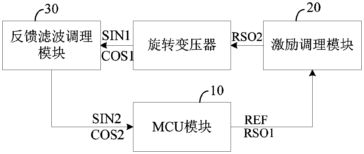
[0015] figure 1 A schematic diagram of the module of the resolver interface device provided by the preferred embodiment of the present invention is shown. For the convenience of description, only the parts related to this embodiment are shown, and the details are as follows:

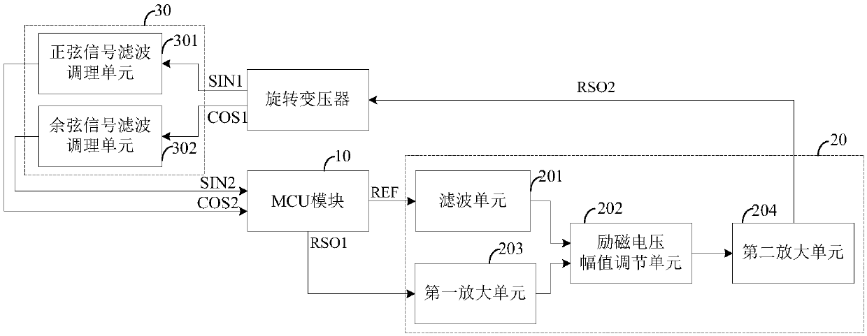
[0016] refer to figure 1 , a rotary transformer interface device, connected with the rotary transformer, including: MCU (Microcontroller Unit, micro control unit) module 10, excitation conditioning module 20 and feedback filter conditioning module 30.

[0017] Among them, the MCU module 10 is used to generate the pulse widt...


PUM


Abstract

The invention discloses a rotary transformer interface device and a frequency converter. The device comprises an MCU module, an excitation conditioning module and a feedback filtering conditioning module. The MCU module generates a pulse width modulation signal with a preset duty ratio and an original excitation voltage according to the target sine and cosine signals; the excitation conditioning module generates a target excitation voltage according to the pulse width modulation signal and the original excitation voltage signal, so that the rotary transformer generates an original sine and cosine signal according to the target excitation voltage; and the feedback filtering conditioning module generates a target sine and cosine signal according to the original sine and cosine signal. The MCU module can output a pulse width modulation signal with a corresponding duty ratio and an original excitation voltage according to the amplitude of a target sine and cosine signal so as to adjust theoriginal sine and cosine signal. Therefore, the target sine and cosine signals are within the decoding range of the MCU module, the problem that in a traditional scheme, conditioning circuit parameters need to be changed manually for rotary transformers with different transformation ratios is solved, a special decoding chip can be omitted, a PCB is reduced, and the product cost is also reduced.

Description

technical field [0001] The invention belongs to the technical field of electromechanical control, and in particular relates to a rotary transformer interface device and a frequency converter. Background technique [0002] At present, in frequency converters, servo drives and other products, resolvers are usually used to measure the rotor position. In order to adapt to resolvers with different transformation ratios, it is necessary to change the gain of the feedback filter conditioning circuit; however, changing the gain requires recalculation of circuit parameters, receiving Materials and replacement with professional welding tools can only be done by professionals; in addition, the interface circuit of the resolver needs to use a dedicated decoding chip, such as: Tamagawa AU6802N1 or ADI’s AD2S1200, but these dedicated chips are not only costly, but also bulky , It will take up a lot of space on the PCB board during circuit design. [0003] Therefore, the resolver interfac...

Claims


Application Information

Patent Timeline
Patent Type & Authority Applications(China)
IPC IPC(8): G01D5/14G05B19/042
CPCG01D5/14G05B19/0425G05B2219/2612
Inventor 马利李慧珍黄主明周军辉
Owner 厦门蓝海华腾电气有限公司
Learn More