Foot tube combined punching machine

A punching machine and leg tube technology, applied in the field of leg tube combination punching machines, can solve the problems of reducing buffer hole efficiency, inconvenient punching die replacement, etc., to achieve the effect of facilitating punching work and improving efficiency

Inactive Publication Date: 2020-08-07
YONGKANG JINOU MACHINERY CO LTD
View PDF9 Cites 0 Cited by
  • Summary
  • Abstract
  • Description
  • Claims
  • Application Information

AI Technical Summary

Problems solved by technology

The current punching machine is not convenient to replace the punching die according to the actual punching needs, which increases the tedious work of punching and slows down the punching efficiency

Method used


Image

  • Foot tube combined punching machine
  • Foot tube combined punching machine
  • Foot tube combined punching machine

Examples


Embodiment Construction

[0020] The following will clearly and completely describe the technical solutions in the embodiments of the present invention with reference to the accompanying drawings in the embodiments of the present invention. Obviously, the described embodiments are only some, not all, embodiments of the present invention. Based on the embodiments of the present invention, all other embodiments obtained by persons of ordinary skill in the art without making creative efforts belong to the protection scope of the present invention.

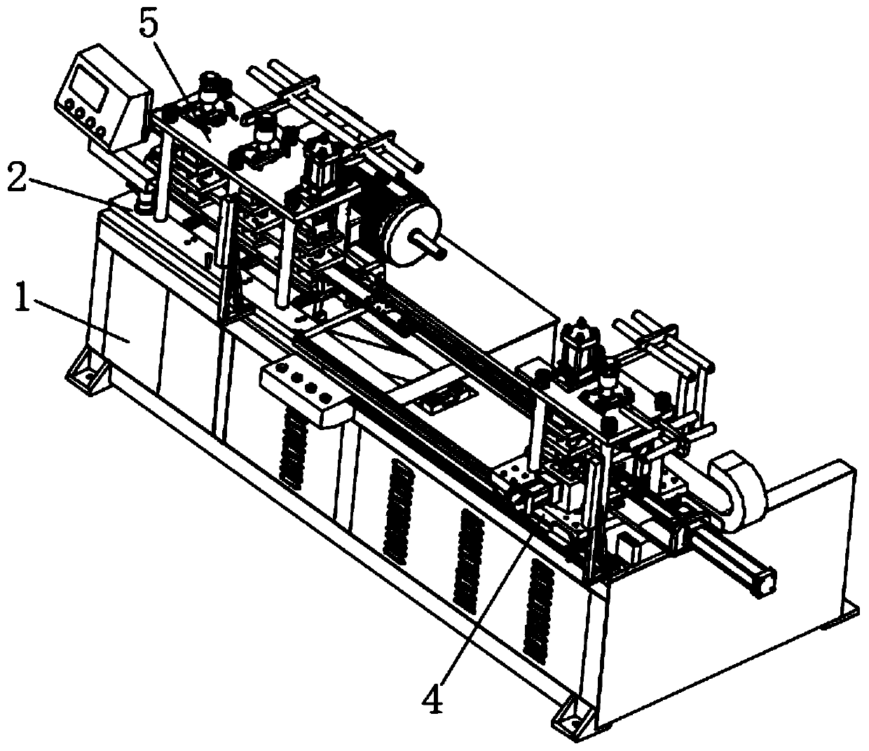
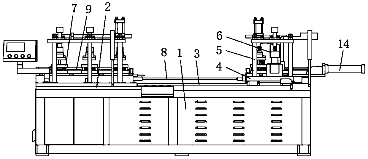
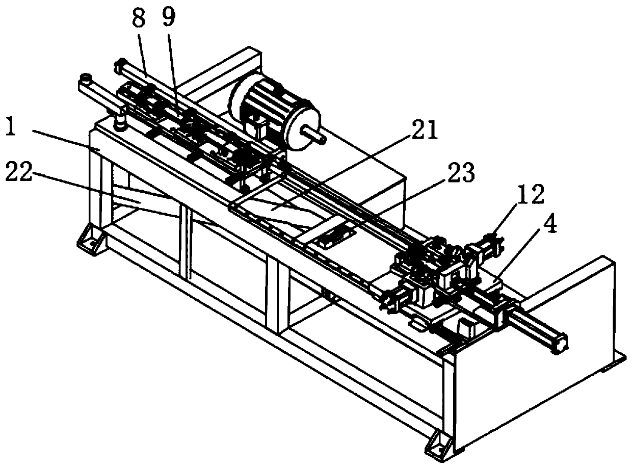
[0021] see Figure 1~6 , the present invention provides a technical solution: a foot tube combination punching machine, including a frame 1, a bottom plate 2 and a slide rail 3 are installed on the top of the frame 1, and a slide plate 4 is slidably connected to the top of the slide rail 3, and the slide plate 4 and the top of the bottom plate 2 are all equipped with a support 5, the top of the support 5 is provided with some punching units, the punching unit ...


PUM


Abstract

The invention discloses a foot tube combined punching machine. The foot tube combined punching machine comprises a rack, wherein a bottom plate and a slide rail are mounted on the top of the rack; thetop of the slide rail is in sliding connection with a slide plate; the tops of the slide plate and the bottom plate are fixedly connected with mounting plates; the end part of each mounting plate isseparately equipped with a first mould and a second mould through bolts; the two sides of the top of the slide plate are equipped with air cylinders; output shafts of the air cylinders are equipped with clamping plates; one end of the top of the slide plate is equipped with a second hydraulic cylinder; a push rod is mounted on the output shaft of the second hydraulic cylinder; and the end part ofthe push rod is positioned at the two sides of the second mould. According to the foot tube combined punching machine disclosed by the invention, the first mould and the second mould are mounted on the mounting plates through the bolts according to the practical needs, so that mould replacement can be completed; and the position of a third hydraulic cylinder is regulated corresponding to a punching mould, so that efficiency of replacing the punching mould is improved, punching work is conveniently performed on different foot tubes, and punching work of foot tubes of different lengths is convenient.

Description

technical field [0001] The invention relates to the technical field of punching machines, in particular to a combined punching machine for legs and tubes. Background technique [0002] Punching machine is a kind of mechanical equipment that after the raw material is installed, driven by the power mechanism, the punching die acts on the material to complete the punching. The current punching machine is inconvenient to replace the punching die according to the actual punching needs, which increases the cumbersome punching work and slows down the punching efficiency. Contents of the invention [0003] The purpose of the present invention is to provide a combined punching machine for legs and tubes. Install the first mold and the second mold on the mounting plate through bolts to complete the replacement of the molds, and then adjust the position of the third hydraulic cylinder corresponding to the punching mold , improving the efficiency of replacing punching dies, so as to ...

Claims


Application Information

Patent Timeline
Patent Type & Authority Applications(China)
IPC IPC(8): B21D28/28B21D37/04
CPCB21D28/28B21D37/04
Inventor 张喜谭鹏侯满进宋俊超
Owner YONGKANG JINOU MACHINERY CO LTD
Why Eureka
Try Eureka