Multi-source cascade heat transfer method
A cascaded heat exchange and heat exchanger technology, which is applied in heating methods, heat pumps, household heating, etc., can solve problems such as poor comfort, high energy consumption, and insufficient use of natural cold sources, so as to improve the efficiency of the grading system and fully Utilize and reduce the effect of supply air temperature difference
- Summary
- Abstract
- Description
- Claims
- Application Information
AI Technical Summary
Problems solved by technology
Method used
Image

Examples
Embodiment 1
[0029] Example 1: Multi-source Cooling Heating System for Water by Medium
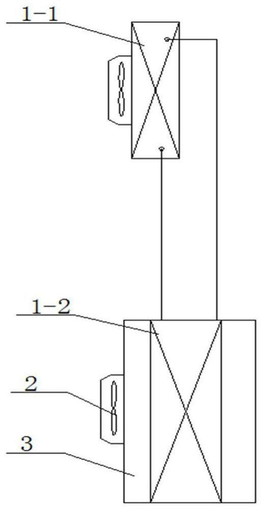
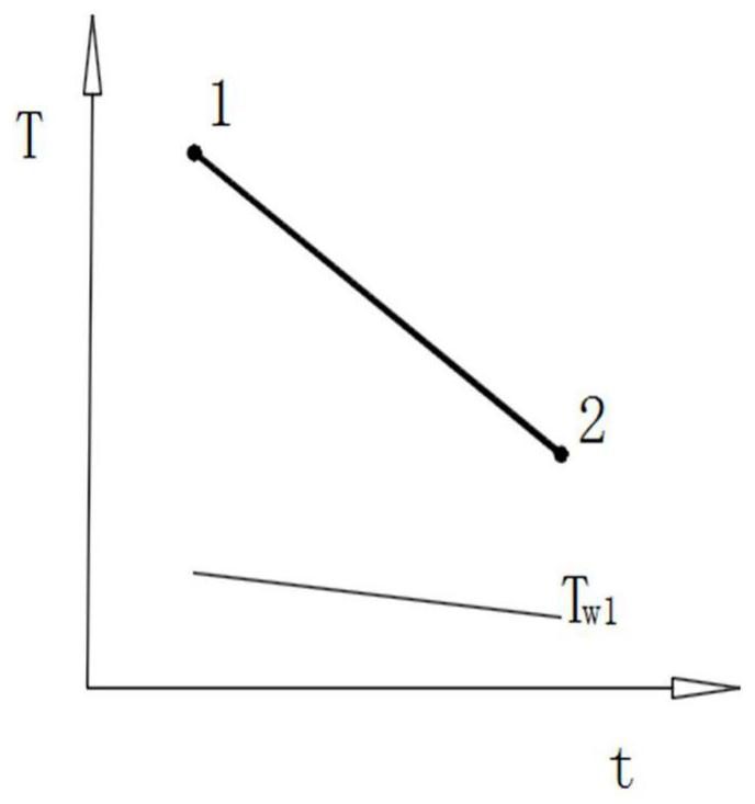
[0030] Such as figure 1 As shown, the single-stage cooling heat exchange system is composed of a refrigeration unit 1-1, a heat exchanger 1-2, a fan 2 and a casing 3, and the heat exchange area of the heat exchanger 1-2 is f, and the heat exchange amount is Q. , The air volume of mass M is powered by the temperature value T 1 Cool to temperature value t 2 Assume that T 1 -T 2 = 10 ° C, T 1 = 32 ° C, cold source medium temperature T w1 = 12 ° C, air treatment process figure 2 As shown, the air is cooled to the status point 2 at a certain time t in the state point 1. The mass flow of the cold source medium is G.
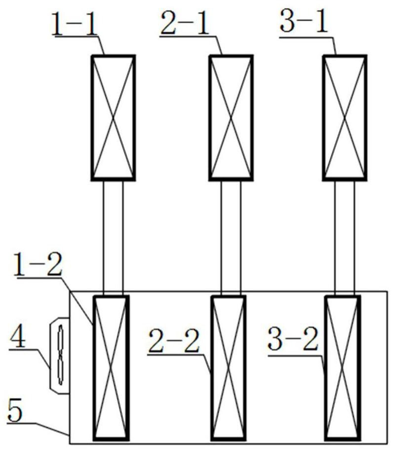
[0031] In order to improve the energy saving efficiency of the system, reduce energy consumption, divide the single-stage cooling heat transfer system into a 3-stage multi-source cooling heat exchange system, total heat transfer Q, the air volume M is unchanged, eliminating the level 1 heat excha...
Embodiment 2
[0039] Example 2: Multi-source step heating heat exchange system for use using media
[0040] The single-stage heating heat exchange system is the same as the single-stage cooling heat exchange system. figure 1 As shown, the single-stage heating heat exchange system is composed of a heating unit 1-1, a heat exchanger 1-2, a fan 2, and a box body 3, and the heat exchange area of the heat exchanger 1-2 is f, and the heat exchange amount is Q, the air volume of mass M is passed from the temperature value T 1 Heat to the temperature value T 2 Assume that T 2 -T 1 = 10 ° C, T 1 = 20 ° C, T R1 = 45 ° C, air treatment process Figure 6 As shown, the air is heated to state points 2 at a certain time t in the state point 1. The mass flow of the heat source medium is G.
[0041] In order to improve the energy saving efficiency of the system, reduce energy consumption, divide the single-stage heating heat exchange system into a 3-stage multi-source strata heating heat exchange system, total...
Embodiment 3
[0048] Example 3: Dual source step heat exchange system for use in the use of media
[0049] Single-stage cooling system such as figure 1 As shown, the system is composed of a refrigerator group 1-1, a heat exchanger 1-2, a fan 2, and a box body 3, and the heat exchange area of the heat exchanger 1-2 is f, and the cooling amount is Q, and the mass is M. The air volume is from the temperature value T 1 Cool to temperature value t 2 Assume that T 1 -T 2 = 10 ° C, T 1 = 32 ° C, T w1 = 12 ° C, air treatment process figure 2 As shown, the air is cooled to the status point 2 at a certain time t in the state point 1. The mass flow of the cold source medium is G.
[0050] In order to improve the energy efficiency of the system, reduce energy consumption, divide the single-stage cooling system into a secondary step cooling and heat exchange system, total heat transfer Q, the air volume M is unchanged, the second level of water supply is g, the second level heat transfer The heat transfer...
PUM
 Abstract
Description
Claims
Application Information
 - R&D
- Intellectual Property
- Life Sciences
- Materials
- Tech Scout
- Unparalleled Data Quality
- Higher Quality Content
- 60% Fewer Hallucinations
Browse by: Latest US Patents, China's latest patents, Technical Efficacy Thesaurus, Application Domain, Technology Topic, Popular Technical Reports.
© 2025 PatSnap. All rights reserved.Legal|Privacy policy|Modern Slavery Act Transparency Statement|Sitemap|About US| Contact US: help@patsnap.com