
Rotor wheel disk assembly structure

An assembly structure and rotor wheel technology, applied in the direction of machines/engines, blade support elements, mechanical equipment, etc., can solve problems such as damage to structural integrity, pits caused by extrusion, and damage to the drum of the first-stage rotor disc

Pending Publication Date: 2020-08-04
AECC SHENYANG ENGINE RES INST
View PDF9 Cites 4 Cited by
  • Summary
  • Abstract
  • Description
  • Claims
  • Application Information

AI Technical Summary

Problems solved by technology

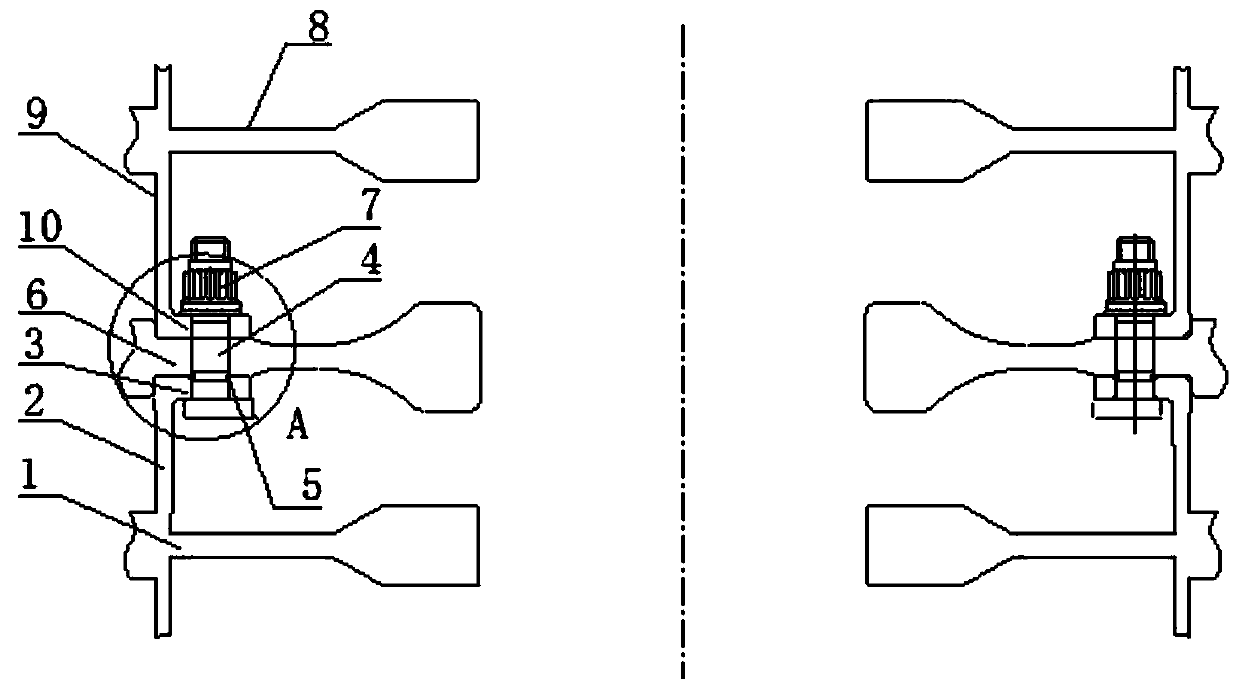
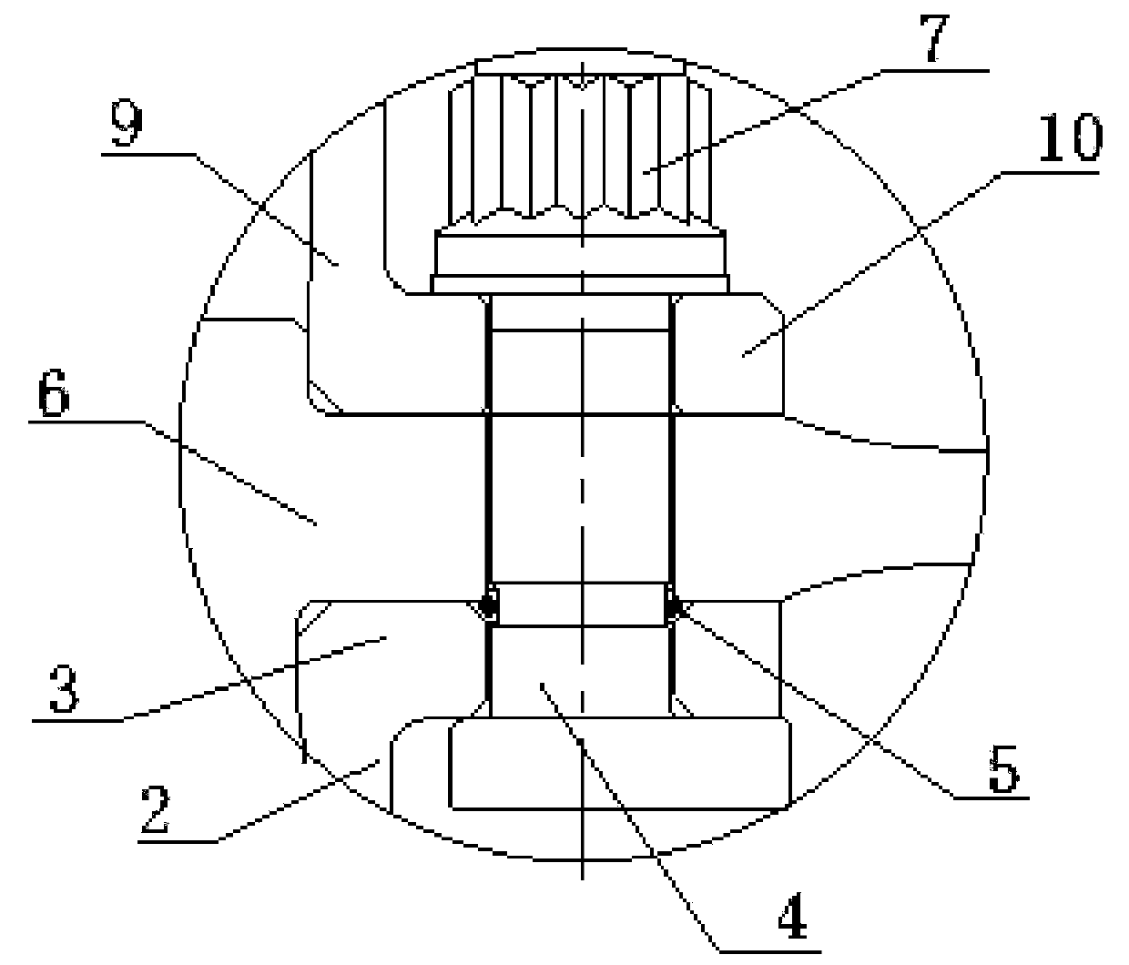
[0003] At present, in the assembly process of the rotor discs at all levels, in order to ensure that the bolts do not fall off, most of the stop hooks are set on the head of the bolts, and the stop bosses are set on the first-stage rotor disc drum to prevent the hooks from falling off. The form of cooperating with the stop boss prevents each bolt from falling off. This kind of bolt with stop hook is easy to squeeze the drum of the first-stage rotor during disassembly and assembly, causing damage to the drum of the first-stage rotor. In severe cases, pits will be squeezed on the drum of the first-stage rotor disc, destroying the structural integrity; in order to prevent the rotation of each bolt when the nuts are used to fasten the rotor discs of each level, the heads of each bolt are mostly The design of the center is D-shaped, and its side is attached to the drum of the first-stage rotor disc, so as to prevent the rotation of each bolt when the nuts are used to fasten the rotor discs of each stage. The middle head is D-shaped. The bolts are also easy to squeeze the first-stage rotor disc drum during disassembly and assembly, causing damage to the first-stage rotor disc drum, and in severe cases, they will squeeze and produce pits on the first-stage rotor disc drum, destroying the integrity of the structure sex

Method used


Image

  • Rotor wheel disk assembly structure
  • Rotor wheel disk assembly structure
  • Rotor wheel disk assembly structure

Examples


Embodiment Construction

[0032] In order to make the technical solution of the present application and its advantages clearer, the technical solution of the present application will be further clearly and completely described in detail below in conjunction with the accompanying drawings. It can be understood that the specific embodiments described here are only part of the application Examples are only used to explain the present application, not to limit the present application. It should be noted that, for the convenience of description, only the parts related to the present application are shown in the drawings, and other relevant parts can refer to the general design. In the case of no conflict, the embodiments in the application and the technologies in the embodiments Features can be combined with each other to obtain new embodiments.

[0033] In addition, unless otherwise defined, the technical terms or scientific terms used in the description of the application shall have the usual meanings und...


PUM


Abstract

The invention belongs to the technical field of engine rotor wheel disk assembly design, and particularly relates to a rotor wheel disk assembly structure. The assembly structure comprises a primary rotor wheel disk, a plurality of connecting bolts, a plurality of clamping rings, a secondary rotor wheel disk and multiple connecting nuts, wherein the primary rotor wheel disk is provided with a primary drum, the primary drum is provided with a primary connecting edge, and the primary connecting edge is provided with a plurality of primary connecting holes formed in the circumferential direction;each connecting bolt correspondingly penetrate through one primary connecting hole, the head portions of the connecting bolts are located on the inner side of the primary drum, and annular clamping grooves are formed in the connecting bolts; each clamping ring is correspondingly clamped into one annular clamping groove; the secondary rotor wheel disk is provided with a plurality of secondary connecting holes in the circumferential direction; the portion, extending out of the corresponding primary connecting hole, of each connecting bolt correspondingly penetrates through one secondary connecting hole; each clamping ring is located between the primary connecting edge and the secondary rotor wheel disk; and each nut is correspondingly in threaded connection with one connecting bolt.

Description

technical field [0001] The application belongs to the technical field of engine rotor disc assembly design, and in particular relates to a rotor disc assembly structure. Background technique [0002] The rotor discs at all levels of the engine are mostly connected by bolts. Due to the limitation of structural space, it is not allowed to assemble the rotor discs at all levels first and then use bolts to fasten them. Instead, install each bolt to the first-stage rotor first. In the connecting holes on the connecting side of the drum of the wheel disc, under the condition that each bolt does not fall off, install the rotor discs of the next stages in sequence, so that each bolt passes through the connecting hole on it, and then use the nuts The rotor discs of all levels are fastened to realize the assembly and assembly of the rotor discs of each level. When the nuts are used to fasten the rotor discs of all levels, it is necessary to prevent the rotation of each bolt. [0003]...

Claims


Application Information

Patent Timeline
Patent Type & Authority Applications(China)
IPC IPC(8): F01D5/06
CPCF01D5/066
Inventor 吴哲马晓健姜永强刘冬韩方军
Owner AECC SHENYANG ENGINE RES INST
Learn More