An adjustable medical stretcher
An adjustable, stretcher technology, used in stretchers, medical transportation, and vehicle rescue, etc., can solve problems such as space occupation, patient life danger, and secondary injury to the wounded.
- Summary
- Abstract
- Description
- Claims
- Application Information
AI Technical Summary
Problems solved by technology
Method used
Image
Examples
specific Embodiment approach 1
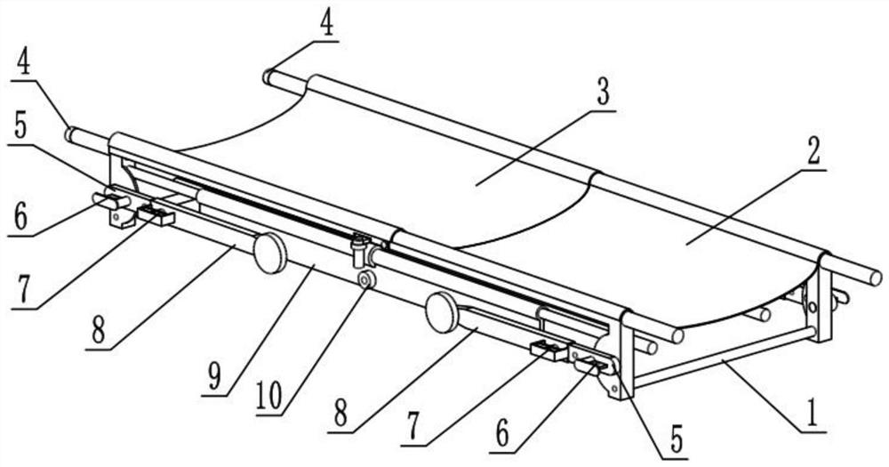
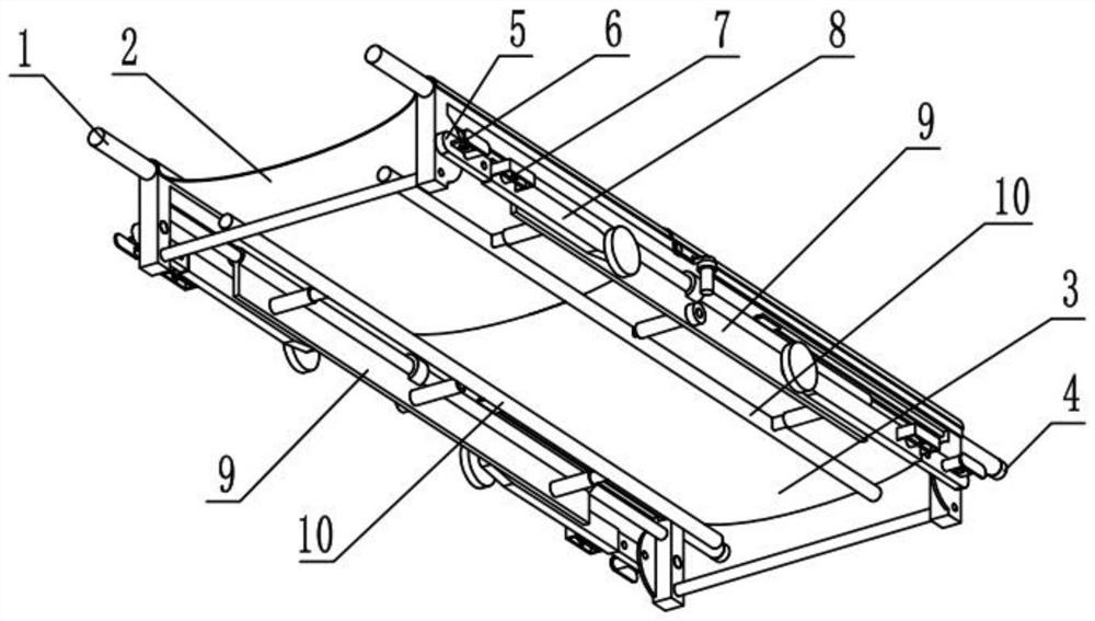
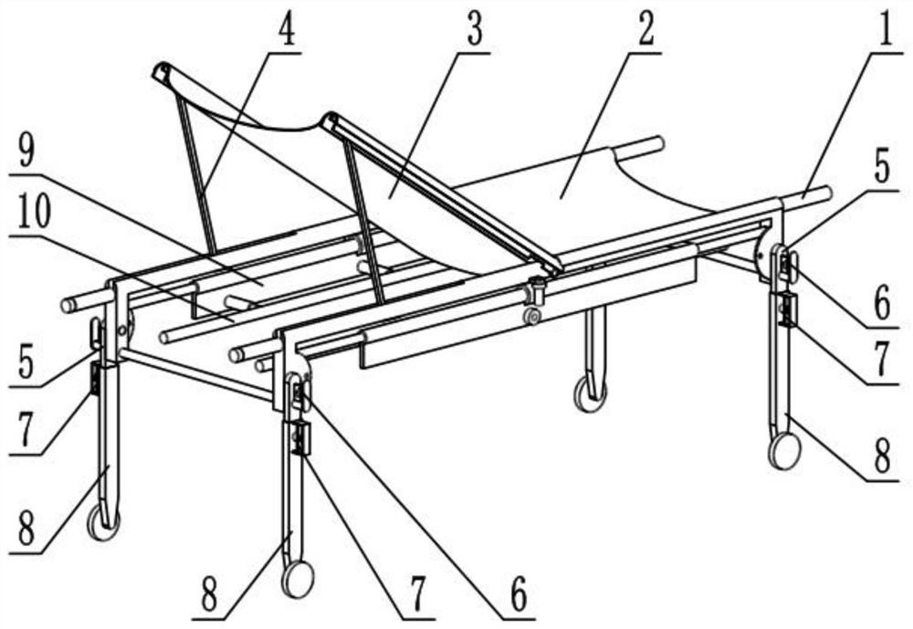
[0028] like Figure 1-11 As shown, an adjustable medical stretcher includes a support frame 1, a lower body support 2, an upper body support 3, a leaning mechanism 4, a leg mechanism 5, a leg locking mechanism 6, a moving leg adjustment mechanism 7, a moving leg 8, The turret 9 and the side bracket 10, the right end of the support frame 1 is fixedly connected with the lower body support 2, the described leaning mechanism 4 is provided with two, and the two leaning mechanisms 4 are respectively connected on both sides of the left end of the support frame 1, The two ends of the upper body towel 3 are fixedly connected with two leaning mechanisms 4 respectively, and the four supporting leg mechanisms 5 are provided with four, and the four supporting leg mechanisms 5 are connected to the four corners of the support frame 1 in rotation respectively, and the four supporting legs The mechanism 5 is connected with a leg locking mechanism 6, and the four leg locking mechanisms 6 are al...
specific Embodiment approach 2
[0030] like Figure 1-11 As shown, the support frame 1 includes a load-bearing beam 1-1, a fixed pin 1-2, a slideway 1-3, a fixed shaft 1-4, a handle 1-5, a support column 1-6, and a semicircular plate 1-7 , crossbeam bar 1-8 and mounting plate 1-9, load-bearing beam 1-1 is provided with two, and the middle part of two load-bearing beams 1-1 is all fixedly connected with fixing pin 1-2, and the middle part of two load-bearing beams 1-1 Slideways 1-3 are provided on the left side, handles 1-5 are fixedly connected to the left and right ends of the two load-bearing beams 1-1, and support columns 1 are fixedly connected to the left and right sides of the lower ends of the two load-bearing beams 1-1 -6, the two support columns 1-6 at the front end and the two support columns 1-6 at the rear end are fixedly connected with a fixed shaft 1-4, the two support columns 1-6 at the left end and the support column 1-6 at the right end There are beam rods 1-8 fixedly connected between the ...
specific Embodiment approach 3
[0032] like Figure 1-11 As shown, the leaning mechanism 4 includes a rotating semicircular tube 4-1, a linkage seat plate 4-2, a linkage plate 4-3, an adjustment knob 4-4, an adjustment screw 4-5, a slider 4-6 and The rotating plate 4-7, the lower end of the semicircular pipe 4-1 is fixedly connected with two rotating plates 4-7, the interlocking seat plate 4-2 is fixedly connected to the upper end of the semicircular pipe 4-1, and the upper end of the interlocking plate 4-3 It is rotatably connected with the linkage seat plate 4-2, and the slider 4-6 is rotatably connected with the lower end of the linkage plate 4-3. The slider 4-6 is connected to the adjustment screw rod 4-5 through threads, and the adjustment knob 4-4 is fixed. Connected to the left end of the adjusting screw rod 4-5, there are two leaning mechanisms 4, the two adjusting screw rods 4-5 are respectively rotated and connected to the two handles 1-5 at the left end, and the two sliders 4-6 are respectively sl...
PUM
 Abstract
Description
Claims
Application Information
 - Generate Ideas
- Intellectual Property
- Life Sciences
- Materials
- Tech Scout
- Unparalleled Data Quality
- Higher Quality Content
- 60% Fewer Hallucinations
Browse by: Latest US Patents, China's latest patents, Technical Efficacy Thesaurus, Application Domain, Technology Topic, Popular Technical Reports.
© 2025 PatSnap. All rights reserved.Legal|Privacy policy|Modern Slavery Act Transparency Statement|Sitemap|About US| Contact US: help@patsnap.com


