Injection molding mechanical mold capable of achieving rapid positioning

A mold and mechanical technology, applied in the field of injection molds, can solve the problems of reducing the efficiency of the frame mold, easy blockage of threaded holes, and easy thread slippage, etc., to achieve the effect of improving the efficiency of the frame mold, improving the positioning efficiency, and facilitating the height of support

Inactive Publication Date: 2020-07-28
TAIZHOU VOCATIONAL COLLEGE OF SCI & TECH
View PDF3 Cites 2 Cited by
  • Summary
  • Abstract
  • Description
  • Claims
  • Application Information

AI Technical Summary

Problems solved by technology

[0003] At present, most of the existing injection molds require the staff to repeatedly adjust the center position during installation so that the nozzle of the mold and the nozzle of the injection molding machine are on the same axis, which is not only time-consuming but also troublesome. When the template and the fixed template are fastened, threaded holes are usually set in advance on the surface of the injection molding motorized template and the fixed template, and then the pressure plate and the mold are fastened through the threaded rod, but the threaded hole is not only easy to block, but also the thread is easy to slip. It takes a lot of time to adjust the position of the pressure plate, which greatly reduces the efficiency of the mold. Therefore, we have designed a fast-positioning injection molding machine mold to solve the above problems

Method used


Image

  • Injection molding mechanical mold capable of achieving rapid positioning
  • Injection molding mechanical mold capable of achieving rapid positioning
  • Injection molding mechanical mold capable of achieving rapid positioning

Examples


Embodiment Construction

[0028] The following will clearly and completely describe the technical solutions in the embodiments of the present invention with reference to the accompanying drawings in the embodiments of the present invention. Obviously, the described embodiments are only some, not all, embodiments of the present invention. Based on the embodiments of the present invention, all other embodiments obtained by persons of ordinary skill in the art without making creative efforts belong to the protection scope of the present invention.

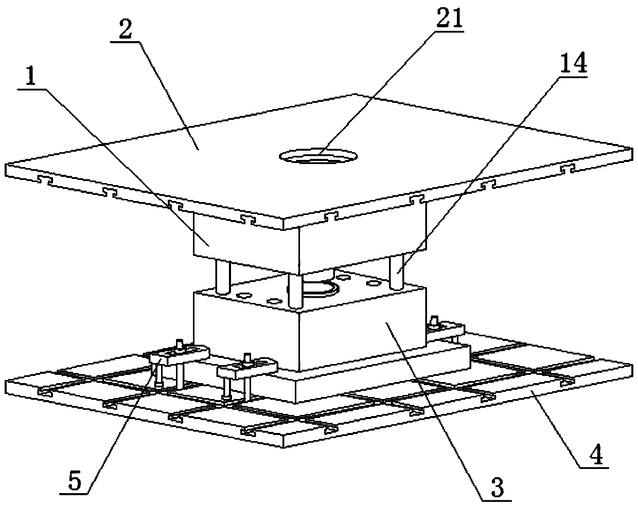
[0029] see Figure 1-5 , a fast-positionable injection molding machine mold, including the upper mold 1, see Figure 1-5 , the upper end of the upper mold 1 is fixedly connected with an upper template 11, and the center position of the upper template 11 is fixedly connected with a positioning sleeve 12. The positioning sleeve 12 is used to fix the center position of the mould, and the center position of the positioning sleeve 12 is provided with a sleeve hole ...


PUM


Abstract

The invention discloses an injection molding mechanical mold capable of achieving rapid positioning, and belongs to the technical field of injection molding molds. An upper mold plate is fixedly connected to the upper end of an upper mold, a positioning sleeve is fixedly connected to the center of the upper mold plate, a sleeve hole is formed in the center of the positioning sleeve, an upper fixing plate is in contact connection with the surface of the upper mold plate, a positioning hole is formed in the center of the upper fixing plate, a guide rod is installed in the upper die, the other end of the guide rod is sleeved with a lower die in a sliding mode, the lower end of the lower die is fixedly connected with a lower die plate, and the lower end of the lower die plate is in contact connection with the lower fixing plate. The upper fixing plate and the lower fixing plate are provided with sliding grooves of the same structure, so that a worker can conveniently and rapidly fasten theupper mold and the lower mold through a pressing plate, the mold erecting efficiency is improved, molds of different sizes can be fixed, and the mold is convenient to disassemble.

Description

technical field [0001] The invention relates to the technical field of injection molds, and more specifically, relates to a mold for injection molding machinery that can be quickly positioned. Background technique [0002] Mold machinery is a tool used to shape objects. This tool is composed of various parts. Different molds are composed of different parts. It mainly realizes the processing of the shape of the object through the change of the physical state of the formed material. [0003] At present, most of the existing injection molds require the staff to repeatedly adjust the center position during installation so that the nozzle of the mold and the nozzle of the injection molding machine are on the same axis, which is not only time-consuming but also troublesome. When the template and the fixed template are fastened, threaded holes are usually set in advance on the surface of the injection molding motorized template and the fixed template, and then the pressure plate an...

Claims


Application Information

Patent Timeline
Patent Type & Authority Applications(China)
IPC IPC(8): B29C45/26B29C45/17B29C45/27
CPCB29C45/1742B29C45/2606B29C45/2708
Inventor 褚建忠解卫华
Owner TAIZHOU VOCATIONAL COLLEGE OF SCI & TECH
Why Eureka
Try Eureka