Positioner

A positioner and motor fixing technology, applied in the field of positioner, can solve the problems of time-consuming, laborious and low efficiency, and achieve the effect of convenient welding work and easy removal

Pending Publication Date: 2020-07-28
益阳百炼链条科技有限公司
View PDF0 Cites 0 Cited by
  • Summary
  • Abstract
  • Description
  • Claims
  • Application Information

AI Technical Summary

Problems solved by technology

[0002] In the traditional welding process, due to the different welding positions, and in order to weld better, the position of the workpiece needs to be adjusted accordingly, while the traditional adjustment of the position of the workpiece is mostly done manually. method, which is time-consuming and laborious, and the efficiency is low

Method used


Image

  • Positioner
  • Positioner
  • Positioner

Examples


no. 1 example

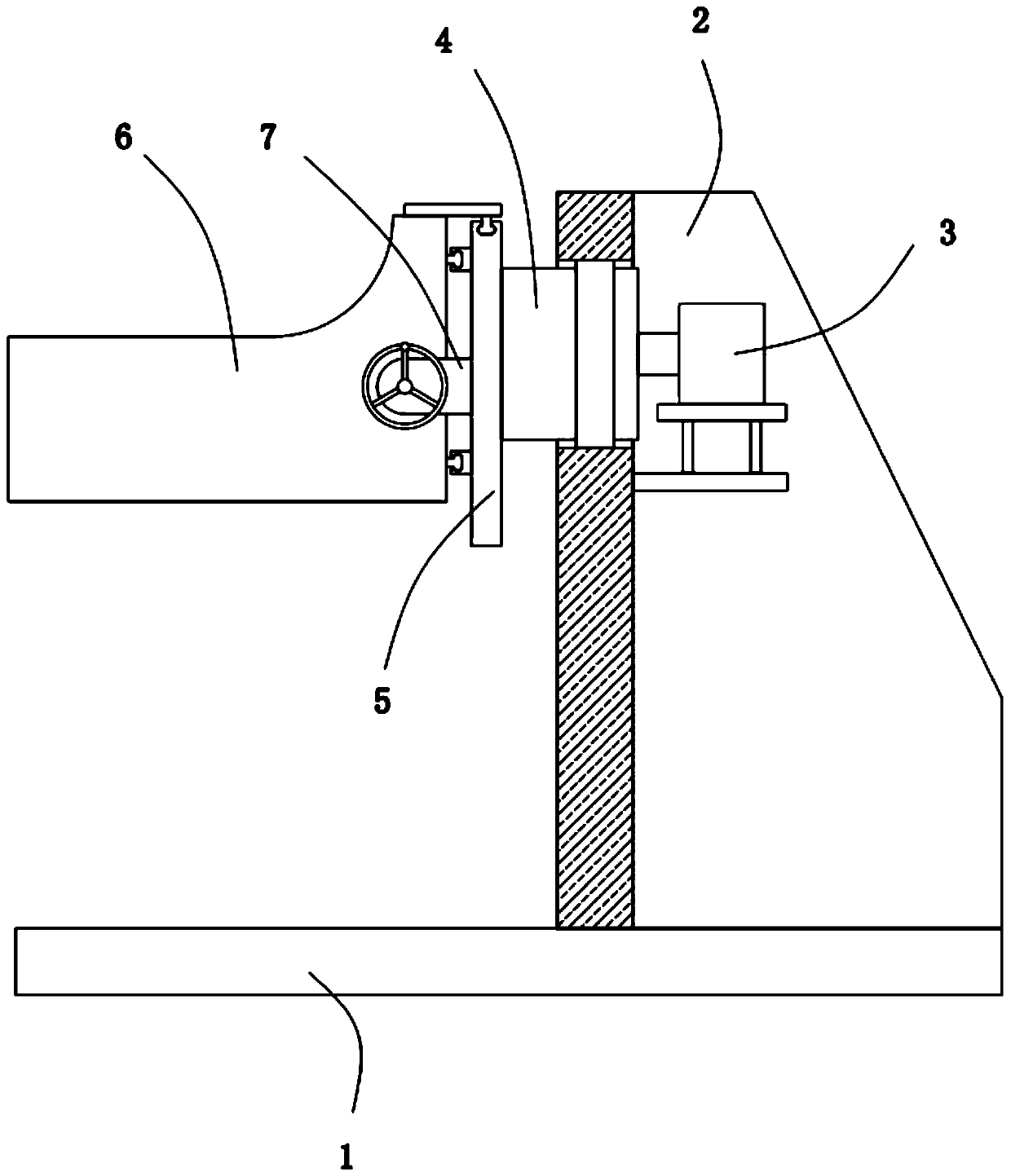
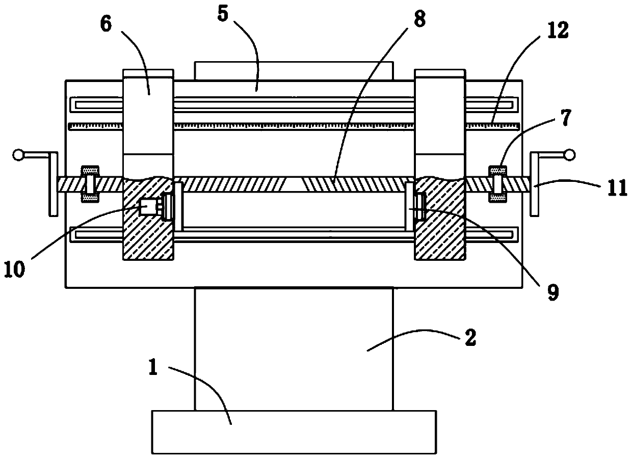
[0024] Please refer to figure 1 and figure 2 , in the first embodiment of the present invention, the positioner includes: a support base 1; a support frame 2, the support frame 2 is fixedly installed on the top of the support base 1; a first motor 3, the first motor 3 is fixedly installed on the support frame 2; the rotating shaft 4, the rotating shaft 4 is rotatably installed on the support frame 2, and one end of the rotating shaft 4 is fixedly connected with the output shaft of the first motor 3; the mounting plate 5. The mounting plate 5 is fixedly mounted on the end of the rotating shaft 4 away from the first motor 3; two clamping arms 6 are slidably mounted on the mounting plate 5 away from the One side of the rotating shaft 4; two rotating seats 7, the two rotating seats 7 are fixedly installed on the side of the mounting plate 5 away from the rotating shaft 4, and the two clamping arms 6 are located on the two rotating between the seats 7; a supporting screw 8, the ...

no. 2 example

[0037] Based on the positioner provided in the first embodiment of the present application, the second embodiment of the present application proposes another positioner. The second embodiment is only a preferred mode of the first embodiment, and the implementation of the second embodiment will not affect the independent implementation of the first embodiment.

[0038] The second embodiment of the present invention will be further described below in conjunction with the drawings and implementation methods.

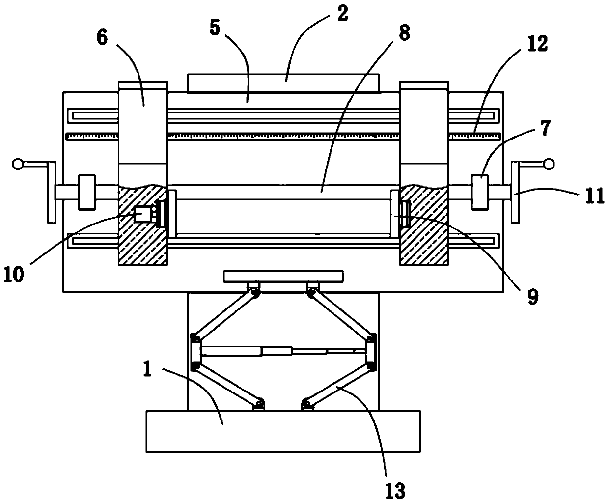
[0039] Please refer to image 3 and Figure 4 , The positioner also includes a lifting mechanism 13 fixedly installed on the top of the support base 1 , the lifting mechanism 13 is adapted to the two clamping rotating blocks 9 .

[0040]The lifting mechanism 13 includes four first hinged rods 14 distributed in a ring, the bottom ends of the first hinged rods 14 are hinged with the top of the support base 1, and the two corresponding first hinged rods 14 is hinged with th...


PUM


Abstract

The invention provides a positioner. The positioner comprises a supporting seat, a supporting frame, a first motor, a rotating shaft, a mounting plate, two clamping arms and two rotating seats, wherein the supporting frame is fixedly mounted at the top of the supporting seat; the first motor is fixedly mounted on the supporting frame; the rotating shaft is rotatably mounted on the supporting frame, and one end of the rotating shaft is fixedly connected with an output shaft of the first motor; the mounting plate is fixedly mounted at the end, away from the first motor, of the rotating shaft; the two clamping arms are slidably mounted on the side, away from the rotating shaft, of the mounting plate; and the two rotating seats are fixedly mounted on the side, away from the rotating shaft, ofthe mounting plate. The positioner has the advantages that using is convenient, operation is easy, a workpiece can be quickly clamped, angle adjustment of the workpiece is facilitated, and thus the workpiece is welded conveniently.

Description

technical field [0001] The invention relates to the field of welding technology, in particular to a positioner. Background technique [0002] In the traditional welding process, due to the different welding positions, and in order to weld better, the position of the workpiece needs to be adjusted accordingly, while the traditional adjustment of the position of the workpiece is mostly done manually. way, time-consuming and labor-intensive, and low efficiency. [0003] Therefore, it is necessary to provide a positioner to solve the above technical problems. Contents of the invention [0004] The technical problem solved by the present invention is to provide a positioner that is easy to use, simple to operate, and can quickly clamp the workpiece, facilitate the angle adjustment of the workpiece, and thus facilitate the welding of the workpiece. [0005] In order to solve the above technical problems, the positioner provided by the present invention includes: a support base...

Claims


Application Information

Patent Timeline
Patent Type & Authority Applications(China)
IPC IPC(8): B23K37/04B23K37/047
CPCB23K37/0435B23K37/047
Inventor 彭万程吴天锡
Owner 益阳百炼链条科技有限公司
Why Eureka
Try Eureka