Convenient-to-use electric control cabinet

An electric control cabinet, a convenient technology, applied in the field of electric control cabinets, can solve problems such as inconvenient use, and achieve the effect of comfortable use, meeting the needs of use, and convenient and labor-saving adjustment process

Inactive Publication Date: 2020-07-24
ANHUI HETIAN ELECTRIC
View PDF7 Cites 1 Cited by
  • Summary
  • Abstract
  • Description
  • Claims
  • Application Information

AI Technical Summary

Problems solved by technology

[0004] The purpose of the present invention is to solve the problem of inconvenient use in the prior art, and propose a convenient electric control cabinet

Method used


Image

  • Convenient-to-use electric control cabinet
  • Convenient-to-use electric control cabinet
  • Convenient-to-use electric control cabinet

Examples


Embodiment 1

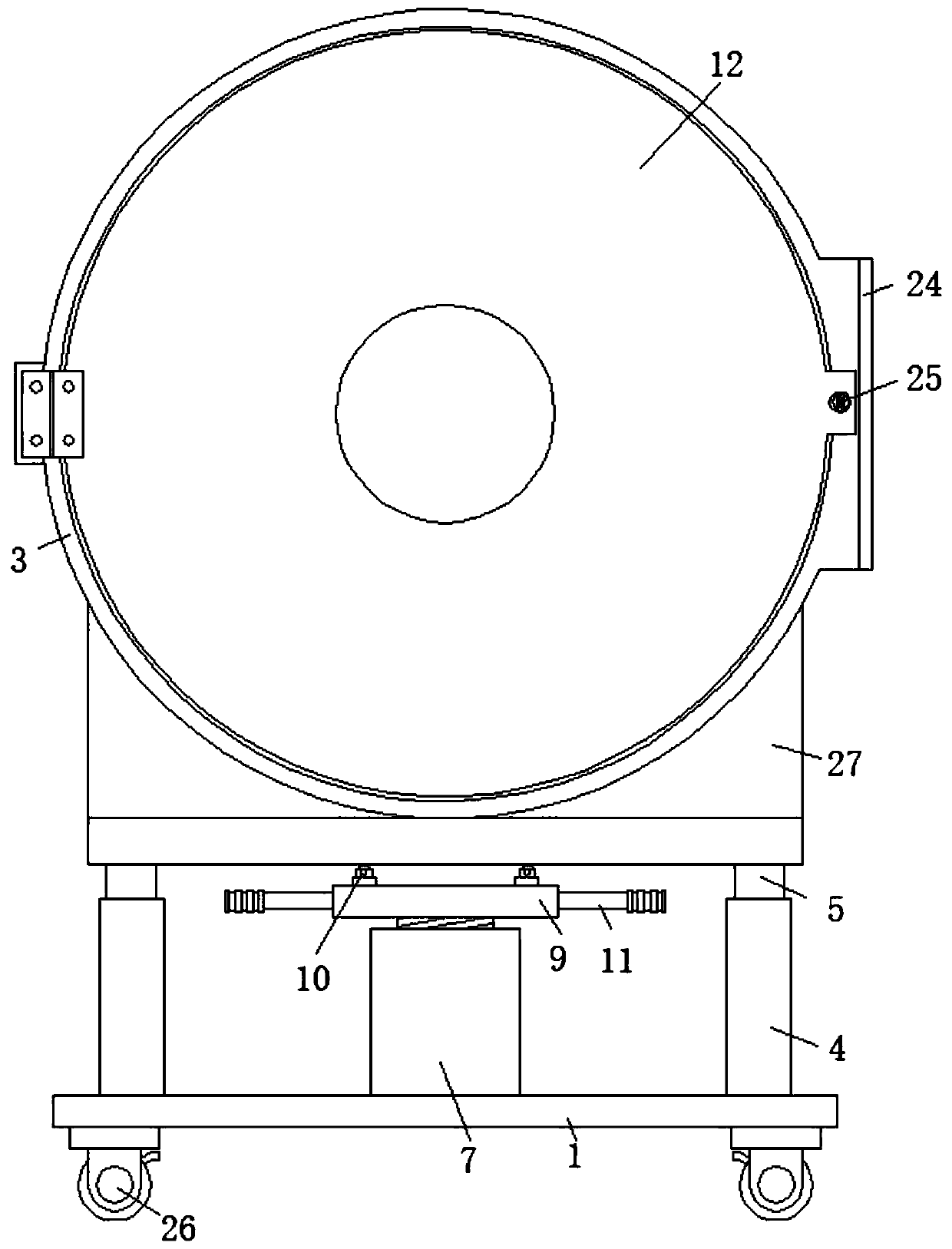
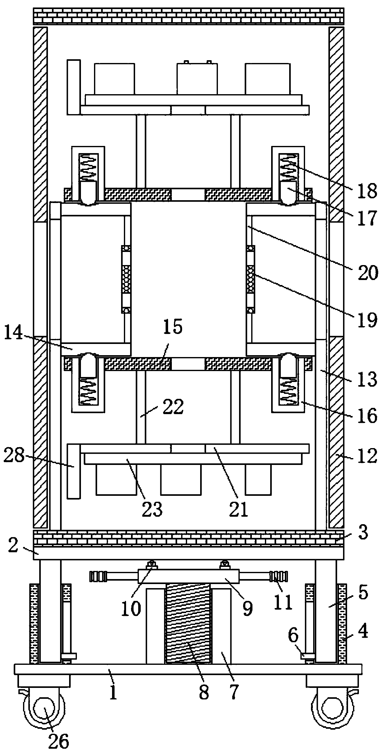
[0027] refer to Figure 1-4 , a convenient electric control cabinet, comprising an electric control cabinet bottom plate 1, a lifting plate 2 is arranged vertically above the electric control cabinet bottom plate 1, an annular shell 3 is fixedly connected to the top side of the lifting plate 2, and the electric control cabinet bottom plate 1 The top side of the lift plate 2 is fixedly connected with a sliding seat 4, the top side of the sliding seat 4 is provided with a top chute, the bottom side of the lifting plate 2 is fixedly connected with a slide bar 5, and the bottom end of the slide bar 5 is slidably connected in the top chute, and One side of the bottom end of the slide bar 5 is fixedly connected to the limiting side bar 6, and the inner wall of the vertical side of the top chute is provided with a side sliding hole, and one end of the limiting side bar 6 slides through the side sliding hole, and the bottom plate of the electric control cabinet 1 The middle part of th...

Embodiment 2

[0030] Such as Figure 1-3 As shown, this embodiment is basically the same as Embodiment 1. Preferably, several handles 11 distributed in a divergent manner are fixedly connected to one vertical side of the support platform 9 .

[0031] In this embodiment, the setting of the handle 11 greatly facilitates people's rotation operation on the support platform 9, thereby making it more labor-saving and convenient for people to adjust the vertical height of the entire electric control cabinet.

Embodiment 3

[0033] Such as Figure 1-3 As shown, this embodiment is basically the same as Embodiment 1. Preferably, door locks 25 are respectively provided between the transparent cover plate 24 and the annular casing 3 and between the two side cover rings 12 and the annular casing 3 .

[0034] In this embodiment, the setting of the door lock 25 greatly improves the safety of the entire electric control cabinet.


PUM


Abstract

The invention discloses a convenient-to-use electric control cabinet, which comprises an electric control cabinet bottom plate, wherein a lifting plate is vertically arranged above the electric control cabinet bottom plate, the top side of the lifting plate is fixedly connected with an annular shell, the top side of the electric control cabinet bottom plate is fixedly connected with a sliding seat, a top sliding groove is formed in the top side of the sliding base, a sliding rod is fixedly connected to the bottom side of the lifting plate, the bottom end of the sliding rod is slidably connected into the top sliding groove, a limiting side rod is fixedly connected to one side of the bottom end of the sliding rod, a side sliding hole is formed in the inner wall of the vertical side of the top sliding groove, one end of the limiting side rod slidably penetrates through the side sliding hole, a threaded cylinder is fixedly connected to the middle of the top side of the electric control cabinet bottom plate, and a threaded column is in threaded connection in the threaded cylinder. Through mutual cooperation of all parts, people can operate and observe electrical elements in the electriccontrol cabinet conveniently, the adjustment process is convenient and labor-saving, and the use requirements of people in production and life are met.

Description

technical field [0001] The invention relates to the technical field of electric control cabinets, in particular to a convenient electric control cabinet. Background technique [0002] Electric control cabinet is to assemble switchgear, measuring instrument, protective device and auxiliary equipment in closed or semiclosed metal cabinet or on screen width according to electrical wiring requirements, and its layout should meet the requirements of normal operation of power system, and is easy to overhaul and does not endanger people. Safety control cabinet (box) for personal and surrounding equipment. Including power distribution cabinets, distribution boxes, electrical control cabinets, etc., the circuit can be connected or disconnected by manual or automatic switches during normal operation. Cut off the circuit or alarm with the help of protective electrical appliances in case of failure or abnormal operation. Various parameters in operation can be displayed by means of mea...

Claims


Application Information

Patent Timeline
Patent Type & Authority Applications(China)
IPC IPC(8): H02B1/30H02B1/50H02B1/52
CPCH02B1/30H02B1/505H02B1/52
Inventor 朱世俊黄春志朱世明
Owner ANHUI HETIAN ELECTRIC
Why Eureka
Try Eureka