Stator blade rotating angle adjusting and measuring structure and calibration method thereof

A technology of stator blade and rotation angle, applied in angle/taper measurement, machine/engine, liquid fuel engine, etc., can solve the problems of inconvenient observation of the piston rod of the actuator, difficult implementation, and low observation efficiency.

Inactive Publication Date: 2020-07-24
AECC SHENYANG ENGINE RES INST
View PDF7 Cites 4 Cited by
  • Summary
  • Abstract
  • Description
  • Claims
  • Application Information

AI Technical Summary

Problems solved by technology

[0004] In order to achieve precise control of the air flow through the compressor, it is necessary to know and accurately control the rotation angle of each stator vane. At present, it is mostly to set the extension length of the piston rod of the actuator in the operating mechanism and the rotation angle of each stator vane. There is a one-to-one correspondence, and the rotation angle of each stator blade can be obtained by observing the extension length of the piston rod of the actuator. Since the extension length of the piston rod of the actuator is not easy to observe, the observation efficiency is low, leading to the adoption of the above technical solution It is difficult to determine and accurately control the rotation angle of each stator blade

Method used


Image

  • Stator blade rotating angle adjusting and measuring structure and calibration method thereof
  • Stator blade rotating angle adjusting and measuring structure and calibration method thereof

Examples


Embodiment Construction

[0037] In order to make the technical solution of the present application and its advantages clearer, the technical solution of the present application will be further clearly and completely described in detail below in conjunction with the accompanying drawings. It can be understood that the specific embodiments described here are only part of the application Examples are only used to explain the present application, not to limit the present application. It should be noted that, for the convenience of description, only the parts related to the present application are shown in the drawings, and other relevant parts can refer to the general design. In the case of no conflict, the embodiments in the application and the technologies in the embodiments Features can be combined with each other to obtain new embodiments.

[0038] In addition, unless otherwise defined, the technical terms or scientific terms used in the description of the application shall have the usual meanings und...


PUM


Abstract

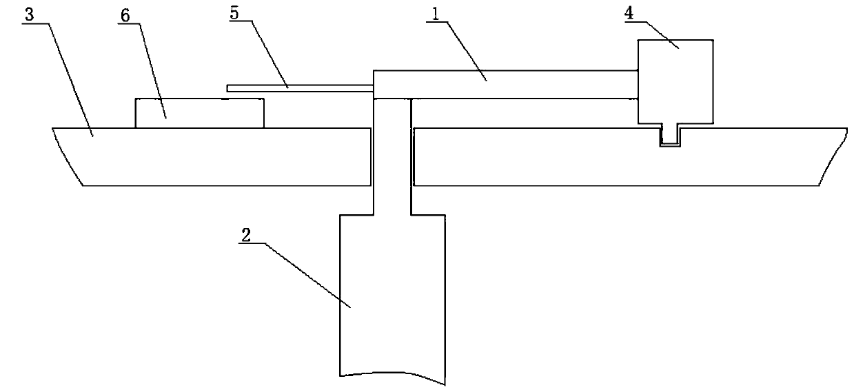
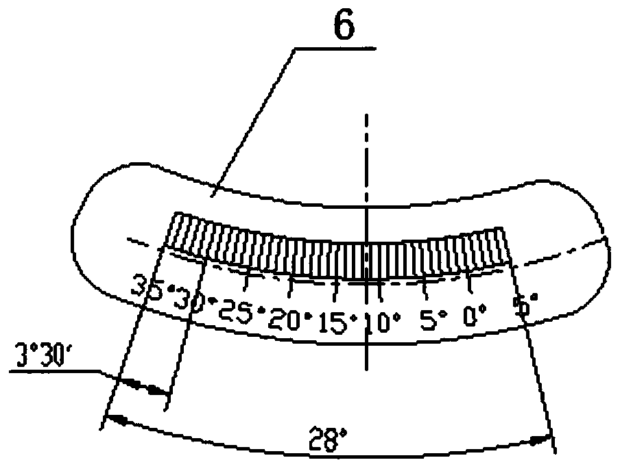
The invention belongs to the technical field of gas compressor stator blade rotating angle measuring, and particularly relates to a stator blade rotating angle adjusting and measuring structure. The stator blade rotating angle adjusting and measuring structure comprises multiple rocker arms, a linkage ring, a pointer and a graduated disc, wherein one end of each rocker arm is correspondingly connected with a part, extending of a gas compressor case, of one stator blade, the linkage ring is connected with the other ends of the rocker arms, is mounted on the gas compressor case in a sleeving manner, can rotate in the circumferential direction of the gas compressor case and drives the rocker arms to swing synchronously, therefore, all stator blades can synchronously rotate, accordingly, angles of the stator blades can be synchronously adjusted, the pointer is connected with one rocker arm, and can swing along with the rocker arm, the graduated disc is mounted on the gas compressor case soas to mark the swing amplitude of the pointer, and the rotating angles of the stator blades can be obtained. In addition, the invention further relates to a calibration method of the stator blade rotating angle adjusting and measuring structure.

Description

technical field [0001] The application belongs to the technical field of measuring the rotation angle of a stator blade of a compressor, and in particular relates to a stator blade rotation angle adjustment and measurement structure and a calibration method thereof. Background technique [0002] In order for the compressor in the engine to work stably, it is necessary to adjust the air flow through the compressor according to the actual situation. For this purpose, the angle of each stator blade in the compressor can be adjusted, and the synchronous rotation of each stator blade can be adjusted through the operating mechanism to change each stator blade synchronously. The rotation angle of the blades is used to adjust the air flow through the compressor. [0003] The existing operating mechanism includes a plurality of rocker arms, linkage rings, and actuators, wherein one end of each rocker arm is correspondingly connected to a part of a stator blade protruding from the com...

Claims


Application Information

Patent Timeline
IPC IPC(8): F04D29/46F04D29/56F04D27/00G01B5/24
CPCF04D27/001F04D27/002F04D29/462F04D29/563G01B5/24
Inventor 张岩蒋琇琇印雪梅王华
Owner AECC SHENYANG ENGINE RES INST
Why Eureka
Try Eureka