
Main frame beam support replacement structure and construction method thereof

A main frame and frame beam technology, which is applied in basic structure engineering, underwater structures, excavation and other directions, can solve the problems of operator replacement of support construction, affecting on-site construction, and high material consumption, and achieves easy construction operation and increased size. The effect of lateral stiffness and construction quality assurance

Active Publication Date: 2020-07-17
CHINA FIRST METALLURGICAL GROUP
View PDF6 Cites 2 Cited by
  • Summary
  • Abstract
  • Description
  • Claims
  • Application Information

AI Technical Summary

Problems solved by technology

In the current construction technology of removing and replacing braces, due to the close distance between the basement exterior wall and the enclosure structure and the deep depth of the foundation pit, operators cannot carry out brace replacement construction in a narrow and dark space, which not only affects the work of the operators, but also The construction quality of the supporting components cannot be guaranteed, which also affects the overall progress of the construction
In order to solve this technical problem, the application number 201910635034.0 discloses a deep foundation pit support assembly type support replacement construction tool and construction method. The base plate, pre-removed internal support, upper pre-installed steel pipe assembly, assembled diagonal brace, lower pre-processed steel pipe assembly, and concrete pier are assembled into a single complete power transmission belt through the above components, but the construction period of this type of power transmission belt is long. It consumes a lot of materials and cannot be used as a permanent support structure. It can only be applied to the bottom plate of the foundation pit, and the scope of application is limited, which affects on-site construction.

Method used


Image

  • Main frame beam support replacement structure and construction method thereof
  • Main frame beam support replacement structure and construction method thereof
  • Main frame beam support replacement structure and construction method thereof

Examples


Embodiment Construction

[0036] The following will clearly and completely describe the technical solutions in the embodiments of the present invention with reference to the accompanying drawings in the embodiments of the present invention. Obviously, the described embodiments are only some, not all, embodiments of the present invention. Based on the embodiments of the present invention, all other embodiments obtained by persons of ordinary skill in the art without making creative efforts belong to the protection scope of the present invention.

[0037] It should be noted that the experimental methods described in the following embodiments, unless otherwise specified, are conventional methods, and the reagents and materials, if not otherwise specified, can be obtained from commercial sources; in the description of the present invention, The terms "landscape", "portrait", "top", "bottom", "front", "rear", "left", "right", "vertical", "horizontal", "top", "bottom", The orientation or positional relations...


PUM


Abstract

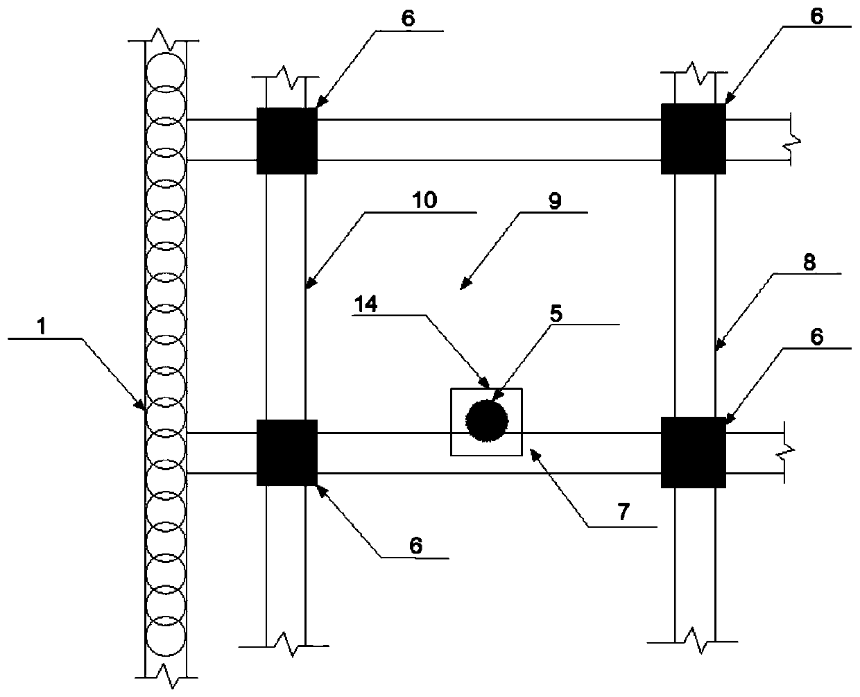
The invention discloses a main frame beam support replacement structure and a construction method thereof. The main frame beam support replacement structure comprises an enclosure structure, an innersupport structure, a main frame structure and a support replacement structure body, and maintenance piles form a closed and independent underground space through occlusion of the piles; the inner support structure supports the enclosure structure before construction of the main frame structure; the main frame structure comprises a frame column, a frame beam, a structural plate and an underground outdoor wall, and the frame beam comprises a transverse frame beam body and a longitudinal frame beam body; and the support replacement structure body is arranged on the transverse frame beam body interfering with a steel vertical column for support replacement and comprises an inclined support replacement beam and a horizontal support replacement beam. A support replacement structural system is designed, when the steel vertical column and the frame beam are overlaid in position and the frame beam cannot transmit the lateral pressure of a foundation pit as a support replacement beam, the support replacement beams are symmetrically constructed on the two sides of the frame beam as support replacement beams, the requirements of safety and stability of the foundation pit are met, and meanwhilethe cost is saved to the greatest extent.

Description

technical field [0001] The invention relates to the technical field of brace replacement construction, in particular to a brace replacement structure of a main frame beam and a construction method. Background technique [0002] The principle of brace-removal construction technology includes two construction steps: brace-replacement and brace-removal. The core of the brace-removal construction technology is to meet the lateral pressure transmission of the foundation pit enclosure structure. In the current construction technology of removing and replacing braces, due to the close distance between the basement exterior wall and the enclosure structure and the deep depth of the foundation pit, operators cannot carry out brace replacement construction in a narrow and dark space, which not only affects the work of the operators, but also The construction quality of the supporting components cannot be guaranteed, which also affects the overall progress of the construction. In orde...

Claims


Application Information

Patent Timeline
Patent Type & Authority Applications(China)
IPC IPC(8): E02D17/04E02D29/045
CPCE02D17/04E02D29/045
Inventor 龚俊肖涛涛徐攀王艳龙陈大为
Owner CHINA FIRST METALLURGICAL GROUP
Learn More