
Rubber strip cutting machine

A cutting machine and rubber strip technology, applied in metal processing and other directions, can solve the problems of self-elasticity and difficult control of cutting precision

Inactive Publication Date: 2020-07-17
深圳市瑞坤自动化设备有限公司
View PDF6 Cites 1 Cited by
  • Summary
  • Abstract
  • Description
  • Claims
  • Application Information

AI Technical Summary

Problems solved by technology

[0002] Most of the existing rubber strip cutting machines use a single stepping motor to control the cutting length. Every time a pulse is sent, the stepping motor rotates an angle to drive the rubber strip to move a certain distance, and then adjust the cutting length of the rubber strip. The disadvantages of control are: it is inevitable that there will be delays in pulse signals, and the cutting accuracy is difficult to control; in addition, the biggest problem is that rubber strips are generally elastic objects, and their own elasticity affects the cutting accuracy when cutting. have a certain impact

Method used


Image

  • Rubber strip cutting machine
  • Rubber strip cutting machine
  • Rubber strip cutting machine

Examples


Embodiment Construction

[0029] Embodiments of the present invention are described in detail below, examples of which are shown in the drawings, wherein the same or similar reference numerals designate the same or similar elements or elements having the same or similar functions throughout. The embodiments described below by referring to the figures are exemplary and are intended to explain the present invention and should not be construed as limiting the present invention.

[0030] In describing the present invention, it should be understood that the terms "length", "width", "upper", "lower", "front", "rear", "left", "right", "vertical", The orientation or positional relationship indicated by "horizontal", "top", "bottom", "inner", "outer", etc. are based on the orientation or positional relationship shown in the drawings, and are only for the convenience of describing the present invention and simplifying the description, rather than Nothing indicating or implying that a referenced device or element...


PUM


Abstract

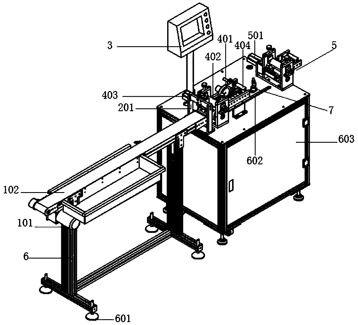
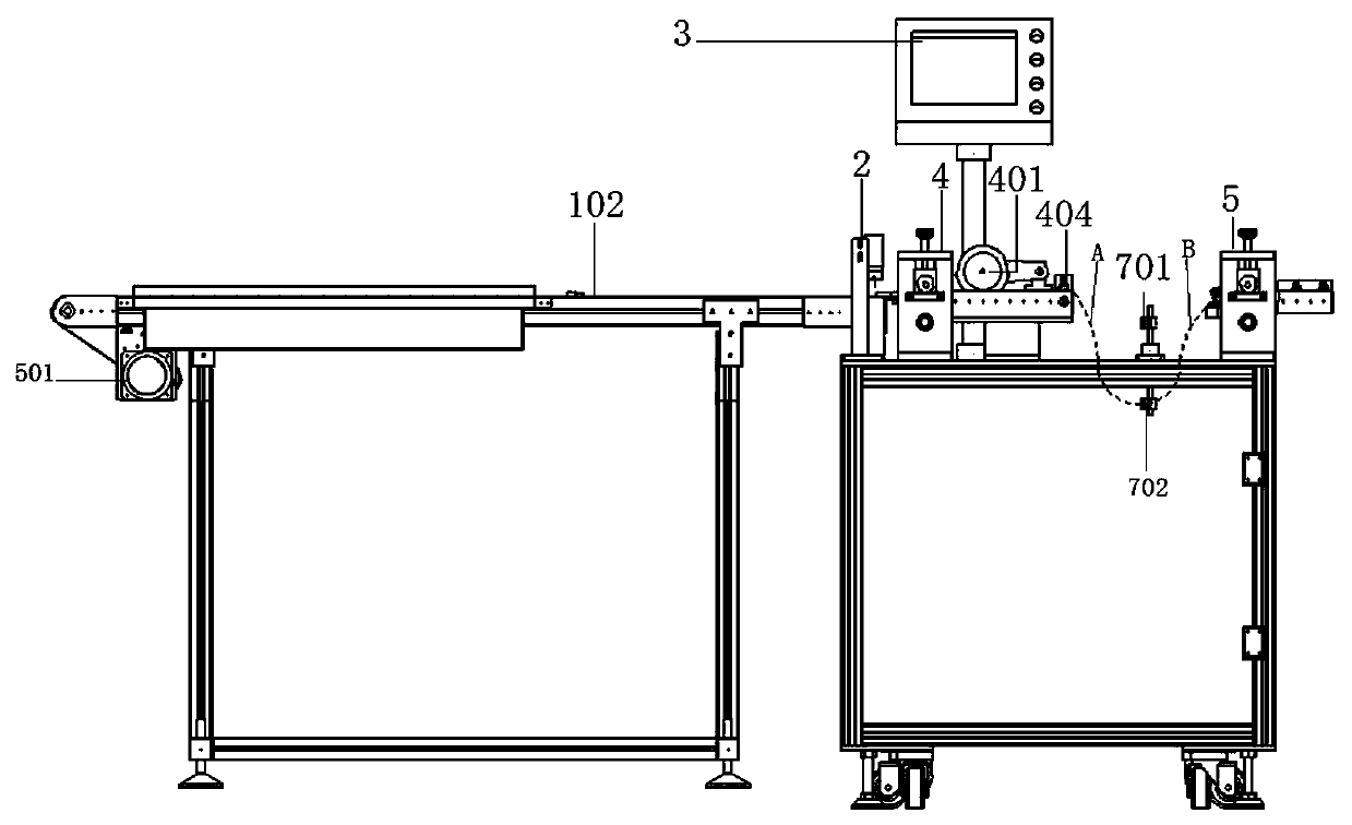
The invention belongs to the technical field of automatic cutting machines and discloses a rubber strip cutting machine for cutting strip materials. The rubber strip cutting machine comprises a firstconveying mechanism and a second conveying mechanism, wherein the first conveying mechanism comprises a first motor and a first locating wheel assembly used for collecting and releasing a rubber strip; the first motor is movably connected with the first locating wheel assembly; the second conveying mechanism comprises a second motor, an encoder assembly and a second locating wheel assembly; the second motor is movably connected with the second locating wheel mechanism; the second motor is used for driving the rubber strip placed on a non-resistance supporting mechanism; the encoder assembly detects the movement state of the rubber strip before being fed into the second locating wheel assembly; on the basis that the second motor accurately controls the moving distance of the rubber strip, the rubber strip cutting machine detects movement of the rubber strip through the encoder assembly, collects and processes data measured by the encoder assembly and rotating data of the first motor andfinally rapidly cuts the rubber strip at the set length.

Description

technical field [0001] The invention belongs to the technical field of automatic cutting machines, and relates to a strip cutting machine for cutting strips. Background technique [0002] Most of the existing rubber strip cutting machines use a single stepping motor to control the cutting length. Every time a pulse is sent, the stepping motor rotates an angle to drive the rubber strip to move a certain distance, and then adjust the cutting length of the rubber strip. The disadvantages of control are: it is inevitable that there will be delays in pulse signals, and the cutting accuracy is difficult to control; in addition, the biggest problem is that rubber strips are generally elastic objects, and their own elasticity affects the cutting accuracy when cutting. cause a certain impact. Contents of the invention [0003] The purpose of the present invention is to address the deficiencies of the prior art and provide a high-density rubber strip cutting machine, which dynamica...

Claims


Application Information

Patent Timeline
IPC IPC(8): B26D1/08B26D5/26B26D7/06B26D7/04B26D7/32B26D7/14
CPCB26D1/08B26D5/26B26D7/04B26D7/0683B26D7/14B26D7/32
Inventor 赵亮亮张辉杨军锋
Owner 深圳市瑞坤自动化设备有限公司
Learn More